Pressure gauges have various types and usage, and one of this was a differential pressure gauge. A differential pressure gauge is not just used to measure and display a pressure reading but it is also used as an instrument to measure the level of a liquid specifically in gas industries (cryogenic).
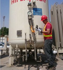
It is used to measure the level of a cryogenic liquid, like Liquid Oxygen (LOX), Liquid Nitrogen (LIN), Liquid Argon (LAR) and others, whether in a storage tank or in a transport tank. These are usually in an enclosed tank.
In this post, I will share with you the following:
- principles about pressure level gauge,
- how to set up before calibration,
- how to calibrate a differential pressure level gauge,
- how to adjust when you encountered an out of specs or not in zero setting,
- how to read a level gauge with multiple displays. Some differential pressure level gauge has a 3 different displayed unit with a varying range. This is confusing if you are not familiar with it.
This post will focus only on the analog type differential pressure level gauge for simplicity.
..
Principles of a Differential Pressure Level Gauge
How does Differential Pressure Determine the Level of Liquid?
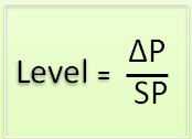
The height or level of a liquid in an enclosed tank can be determined by the differences of two pressures (the high and low side) divided by the specific gravity of the liquid. That is why we are using a differential pressure gauge as the instrument for this job. This is also applicable to an open-end tank or vessel.
The formula below explains how a level is computed when a delta P (ΔP) or differential pressure is available.
Where:
ΔP = P-P1 – the difference of two pressure
Where:
P – Higher Pressure (Wet Leg)
P1- Lower Pressure (Dry Leg)
SΡ – Specific Gravity of the liquid use
Or re-writing the equation, we can determine the pressure by substituting known specific gravity of the liquid multiplied by the level (height) of the liquid. See below equation:
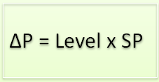
Based on the above equation, we can see that the pressure is dependent on the liquid density or its specific gravity when in use, so different kinds of liquid gas even though they have the same level value will display a different pressure.
It is important that we should determine first the kind of liquid before we can take the exact value of measured pressure with an equivalent value of level.
For more reading about this topic, you may visit this site>>Level Measurement
..
Understanding the Units Displayed in a Differential Pressure Level Gauge
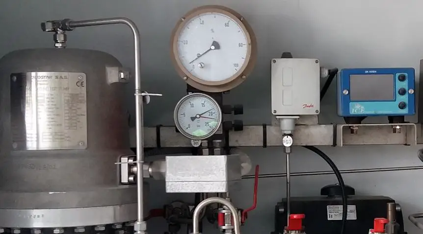
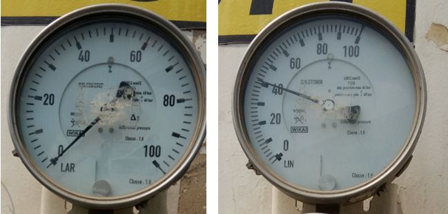
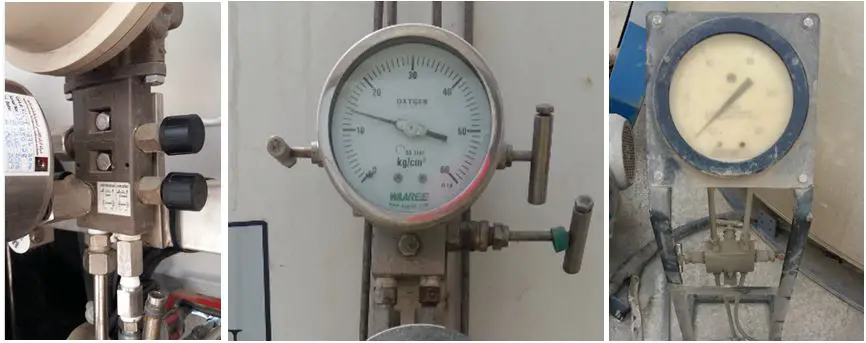
The displayed units we normally encounter are the pressure units which are the mbar or the mmH20 which is also equal to mmWC. Others are directly displayed as percentage % units, volume in Liters, or fraction format to show the actual level, some are in a combination of the two. See photo below.
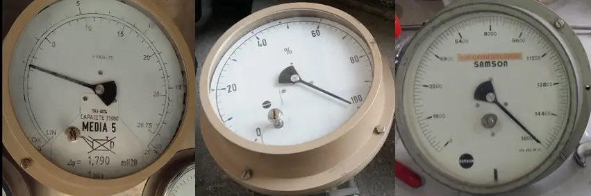
This kind of units or display is very usual and understanding them is very simple.
But what if the display are different, in LOX, LAR or LIN?
There are also Level Gauges that display only a pressure unit in LIN, LOX or LAR ( also known as ArL, OL, and NL) which has an equivalent pressure value depending on the liquid content of the storage tank.
Actually, this is not a pressure unit, but the name of the liquid gas used, namely, Liquid Oxygen (LOX), Liquid Nitrogen (LIN) and Liquid Argon (LAR). Others are CO2 or 02 which are the ones we normally see.
The main unit that is being used is the percentage (%) and it has a pressure value counterpart in mmH20 (mmWC), mbar or in other pressure units. Some level gauge also has a unit of volume, which is in Litre.
Have you encountered a Differential Pressure Level Gauge with multiple ranges or type of liquid gas it can measure?
There is also a level gauge with 3 displayed range or fluid gas used in one face of the gauge with a fraction as its scale division. It may confuse you at first (because it did to me) on its many displays. See below photo.
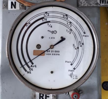
Some level gauges have no pressure units, only the fluid that is being used. Also, some pressure level gauge displays only the full range value of its pressure.
This is why it is important to have in hand the specifications of the tank where it is being used before calibration, in order to determine the pressure displayed versus the equivalent level.
This is provided by the manufacturer or supplier of the instruments used. There are conversions or equivalent pressure value that we need to know in order to understand it.
Below is a sample conversion or reading from manufacturer posted on the storage tank.
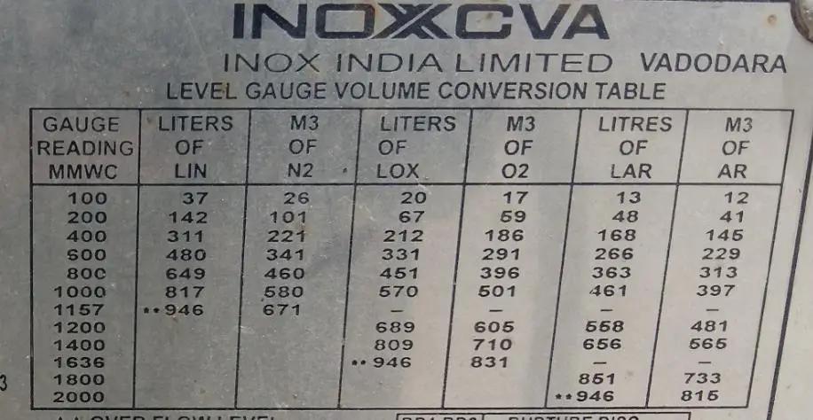
You should be aware of these specifications because not all storage tanks display this information.
How to Read a Differential Pressure Level Gauge?
There are so many types or model or manufacturer of a differential pressure gauge and I will share in this post the one that I encounter and hopefully, it will be a great help to you.
Differential Pressure Level Gauge with a Normal Units of display
I will first introduce the level gauge with a simple pressure to the percentage (%), volume, or direct pressure equivalent reading (see Figure 1 above). These type of Level gauges have a readout display that is directly converted to level. An example is a percentage (%) which means that at a full range of pressure generated equals a 100% level.
I suggest that before performing a calibration, you should be aware of below information:
- The maximum range (some is written on its body)
- How to set the shut-off valves in a 3 valve manifold ( see below)
- The unit of measurement it is being used and their equivalent conversion units.
- The user ranges if available.
By having this information readily available, recording calibration data points can be achieved easily.
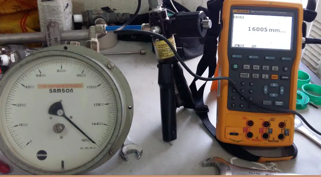
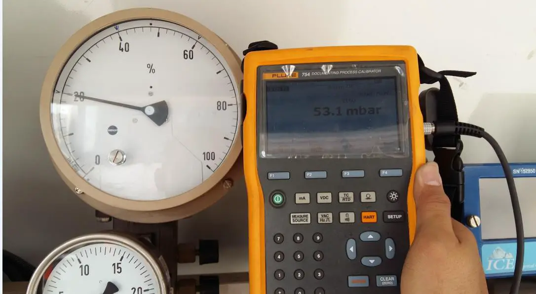
We will calibrate the level gauge by using Fluke 754 with a pneumatic pump and a Pressure Module as our reference standards.
Calibration of this type of a level gauge is exactly the same as a normal Differential Pressure Gauge as long as it is detached from its location and manifold and thereby directly accessing the input (+ side) of the differential level gauge.
The procedure for calibration is the same for the calibration of a differential pressure gauge. You can read it on this link >>Diffrential Pressure Gauge Calibration
Pressure Level Gauge with ArL (LAR), NL (LIN) or OL (LOX) display (for Figure 2 and 3 above)
As explained above, the level is dependent on the specific gravity of the liquid gas that is in use, but during calibration, since we will isolate the level gauge by closing the valves on its manifold or simply removing the level gauge itself, we will use the air (oxygen) as a medium or fluid for calibration or for generating pressure.
The process of reading is still the same as the normal display units above, the only difference is the liquid used. During calibration, we will neglect the liquid gas setting displayed in the unit and substituting 1 as the specific gravity for every pressure value we have (see formula 2 above).
The level gauge output display in this process act as a normal level or differential pressure gauge (unless you use the exact liquid gas they used). So the calculation of level in terms of specific gravity is not needed.
As seen on the table on the photo above (figure 4), every pressure value has a corresponding level value. But since we will be using air as the medium, we only need the full user range setting (the pressure reading) of the level gauge, and from here, we can now determine the exact division of scales in the level gauge and use this as the calibration points directly
.
Pressure Level Gauge with Manifold
In this part, I will share with you how to set up and isolate a differential level gauge with a manifold.
Most level gauge of this type when calibrating on-site or in its location, it is integrated on its manifold and cannot be detached, in this regard, an additional step must be followed in order to properly measure or calibrate the unit.
One must be familiar in the opening and closing its isolation valve in order to achieve the correct reading. This is very tricky when you are not familiar with its manifold. You may also damage the level gauge when a sudden rush of pressure is encountered.
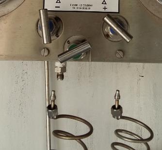
Preparation Before Calibration (Check Zero Setting)
a simple demonstration on how to perform differential pressure level gauge zeroing and calibration set up.
Before performing the calibration, close all valves with pressure going to the manifold and execute the procedure below (See figure) to prepare the level gauge for calibration. There are different designs of manifolds (as you see above) but the valve operation is the same, so don’t get confused with this.
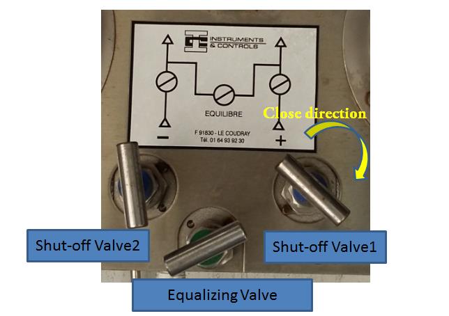
- Close the high-pressure shut-off valve1.
- Open the equalizing valve.
- Close the low-pressure shut-off valve 2.
In this status, the level gauge pointer must also be in Zero position. It is now ready to be calibrated. If not in zero position, perform an adjustment. Read further below.
..
3 Calibration Set-Ups for a Differential Pressure Level Gauge
The Set-Up When it is Removed from its Manifold
The Set-up for a pressure level gauge that is removed from its manifold is also the same as a simple differential pressure gauge so the connections are also the same.
In the case where the Level gauge is detached on its manifold, we will just locate the positive side of the level gauge and connect the input pressure of the reference standard. See below photo.
The Set-Up for Level Gauge with Manifold but with a Dedicated Calibration Port
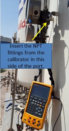
A dedicated calibration port is included in most Differential Pressure (DP) level gauges for ease of calibration without removing the unit from its manifold or assembly.
This makes calibration or verification much easier and faster. You just need to isolate the unit from the pressure source then Perform the “Zero Setting” procedure presented above.
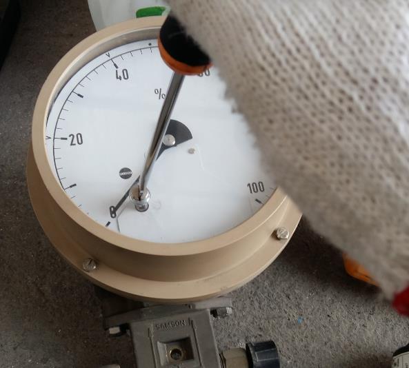
Zeroing will also Isolate the DP level gauge. Once Isolated, remove the seal of the DP level gauge on its side (right side when facing the unit). it has (+) sign in it. See below photo.
There is another seal in the left, the (-) port, just loosened it, no need to remove. Then insert the NPT fittings of the calibrator on the positive port (+). Make sure to close the equalizing valve.
You are now ready for calibration. See below set up.
Set-Up with the 3-Valve Manifold
When manifold is included, you need to follow an additional procedure.
After performing the preparation and zero-check procedure above, it is now time to connect our standard for calibration into the manifold. Follow below steps.
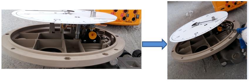
- Ensure that the manifold is Isolated from the supply. Remove all the fittings or connected tubes in the manifold input.
Manifold with detached connections after isolation - Open both the negative and positive shut-off valves of the manifold
- Close the equalizing valves, in this status, the level gauge should be in zero position because the pressure in the positive and negative are exposed to ambient and therefore equal.
- Connect the port of the calibration pump on the positive side of the manifold.
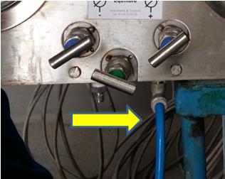
Manifold connected to reference standard output port. - You can now start to pump and generate pressure.
..
DPLG Calibration Procedure
Since this is a Differential Pressure (DP) gauge, we will follow the procedure in calibrating a differential pressure gauge. The only difference is that pressure value must be converted to the level value designated to the level gauge. Below photo shows pressure to percent (%) conversion. (We need to compute)
- Set to zero.
- Generate pressure in an increasing manner until you reached the full scale. This will only require a small pressure so pump very slowly and not to damage the level gauge.
- Then slowly release the pressure and get the reading. Same set point but in a decreasing manner.
- Repeat the process two times.
- Record all readings in your Measurement Data Sheet.
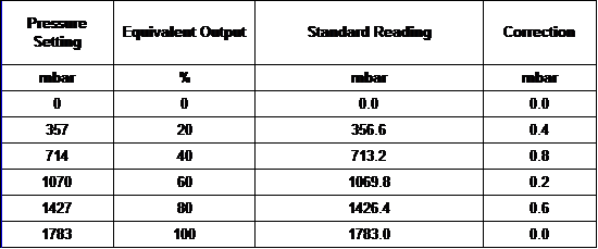
Sample data record with pressure to (%) conversion
Visit my other post to see the complete differential pressure gauge calibration procedure in this link
Returning For Operation – Startup
After calibration and everything is returned for operation, follow the procedure for “Preparation Before Calibration” but in the reverse order. This will ensure that the level gauge is protected from a strong surge of pressure that can damage the unit.
- Open the low shut-off valve2.
- Close the equalizing valve.
- Slowly open the high shut-off valve1.
It is now ready for testing or operation.
..
Calibration Adjustment
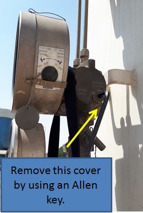
You can perform below adjustment just in case the readings are out of specifications or if the needle is not in the zero position. (for Samson made level gauges)
Other level gauges can be adjusted using the method for a normal pressure gauge. Visit my other post in this link. 5 Techniques for Pressure Gauge Adjustment and Repair
First, use the designated zeroing port. If this fails, perform below, see photo.
- Open the level gauge housing.
- Locate the screw, use an Allen key to turn. (Some unit has Allen key included in the unit).
- Slowly turn clockwise or counterclockwise depending on the offset you need. Remember, Use only a very small force, this is very sensitive.
- Perform another calibration to check the reading.
Conclusion
I have presented what I believe the important aspects during maintenance or calibration of a differential pressure level gauge. We have discussed the principle on how a differential pressure gauge can measure a level that is dependent on the density of the liquid, I have shown you the different types of level gauges display and explained how to understand them, presented the calibration set up, zeroing, and the procedure.
I hope that this could help you in your level gauge calibration.
Thank you for visiting my site, please leave a comment, share and subscribe.
Best Regards,
Edwin
21 Responses
Virgel
Very good article. I hope there is a book or eBook for this. Thank you and God bless.
edsponce
Hi Virgel,
I appreciate you liked the article. Thank you for visiting my site. Yes, I will consider creating an ebook for this.
Best regards,
Edwin
migw
hey how do i get to contact you directly?
edsponce
Hi Migw,
You can email me directly at edwin@calibrationawareness.com or visit my FB page in this link
Thanks for reading my post.
Edwin
Mahmoud Hasan
Thanks for your efforts.
edsponce
Hi Mahmoud,
you are welcome, thank you for reading my post.
Best Regards,
Edwin
Anh Nguyen
Hi Edwin
If I remove DP gauge from manifold for maintenance or change new, I did below step:
1: open equalizing full
2: shut off high(+) pressure valve
3: shut off low(-) pressure valve
What happened it?
Best regards
Anh Nguyen
Ps: my English badly 😂
edsponce
Hi Anh,
Your step is ok. But better to close first the High (+) side before others.
Always start closing with the high (+) pressure side first then to the low (-) side. And to return back, just follow the opposite direction, the high(+) side should be the last valve to be open. This will ensure safety to the DP gauge.
But, if you want to remove the DP gauge totally, It is better to disconnect or isolate it from the main pressure supply to remove safely.
I hope this helps,
Edwin
anjum
how to calculate the oxygen liquid mmwc in cubic meter
edsponce
Hi Anjum,
There is no direct conversion to calculate pressure to a volume that I am aware of. The value of volume (cubic meter) is dependent on the design of the tank or container. You need to check with the manufacturer of the tank. Usually, there is a conversion table like the one I show in my post.
The tank is designed/configured with the level gauge where a pressure reading has an equivalent volume. If you need to calibrate the pressure level gauge, then you need this conversion table in order to verify if the Differential Pressure Level Gauge is Ok.
If you have the minimum and maximum value of the pressure with the equivalent volume (cubic meter). then you can calculate other setpoints in between by using ‘Linear Interpolation’.
I hope this helps,
Edwin
Mitchell Wells
This was a good read sir.
Question: DP level transmitter (3051) with wet leg
3 way valve (coplanar) with bleed/vents
Zero – Trying to determine the proper or most accurate way…
Block isolation valves
Bleed vents on H&L To atmosphere
Open the equalizer
Zero
Or
Block H isolation valve
Open equalizer
Zero
Or
(Not sure if your example in the article applies to this?) —>Block H isolation valve
Open the equalizer
Block L isolation valve
Zero
Thanks.
edsponce
Hi Mitchell,
The first and 3rd are OK. I am not sure about the 2nd.
If your purpose is just to zero out without calibration, while it is still connected complete in the line, you can perform the 3rd procedure you mention.
-Block H isolation valve
-Open the equalizer
-Block L isolation valve
-Zero
But for calibration purposes, you can perform below:
– Isolate pressure source
– Open H valve to atmosphere
– Close the equalizer
– Open L valve to atmosphere
– Zero
– Connect Standard to H valve port (wet leg)
Thanks for sharing your inputs.
Edwin
Nagendra Rao
Good morning sir,
I am Nagendra. Your article is very nice and useful.
Sir, I have one doubt.
I have a Differential Pressure Gauge which is make by HIRLEKAR PRECISION. This Differential Pressure Gauge is using as Level Gauge in LOX system. I removed it from the system which is I am going to Calibrate. This gauge has two ports, oneside is High Pressure (which is written +ve) and another side is Low Pressure (which is written -ve). That gauge range is from “0 to 250” Liters.
My doubtis how to calibrate this type of gauges. Suppose my Testing Points are “28, 50, 100, 160, 220 and 250 Liters”. So how much of pressure give to calibrate of given testing points. Please give me the pressure values of given testing points also tell me that pressure give to which side.
Kindly please help me sir
edsponce
Hi Nagendra,
Thanks for visiting my site.
About your concern, there is no direct conversion of Liters to pressure. You need to have the specifications of the tank. The manufacturer of the tank where the Level Gauge was installed should have the specifications, the equivalent pressure to Liters. See the example in my post above. That is installed in the tank, I believe also available in its manual. I suggest you look for the manual of the tank.
There is an indirect way to convert pressure unit to Liters or other units, this is by determining the value based on the percentage (%) if the full-scale pressure is given. If there is a full-scale pressure value indicated in the gauge, you can convert that to a % unit and at the same time to pressure unit. For example, if the full-scale pressure value is 1000 mmH20 = 100%, you can calculate other equivalent values based on percentage. You expect that at 50%, it should be 500 mmH20 (0.5×1000) also equivalent to 125 (0.5×250) liters, and so on, see below table as an example.
The calibration procedure is simple, it is the same with a normal pressure gauge. Just use the positive side as the input for your standard then leave the negative side to ambient (just open to the environment).
I hope this helps,
Edwin
Abdur Raheem
Hi. Thanks for the article. It was very informative. I have a query regarding a LOX storage tank at our site. Range is from 0-4191 mmwc. As per design data and level chart on tank the overflow should be achieved at 90+ percentage. But upon filling the tank with LOX, at around 70% which is around 2933 mmwc ,tank reached over flow. This overflow at 70% level was continuously observed over many fillings.
We checked the leakage in tubings, didn’t find any. Moreover the local gauge and transmitter values are matching.
And another thing observed is at one point we had 45% level (1885 mmwc). We isolated gauge and transmitter for a couple of days. The tank was static with no filling or removal of LOX. When we took the level gauge and transmitter in line after two days, initially both gauge and transmitter showed 3200 wc(76% in DCS) . But the value starting dropping gradually and reached 1885 mmwc (45%) in 30 minutes which was the level before isolation two days back and after that value stayed constant with no further drop in level.
So would like to understand why the level increased when it was taken in line after two days and later dropped to the initial value.
Does differential level gauges take time to stablize?
Also as far as my first question regarding achieving overflow at 3200 (70%), kindly advice regarding these two queries.
Thanks a lot.
edsponce
Hi Abdur,
You are welcome and thank you also for reading my posts.
Regarding your concerns, I cannot provide an indepth advise because my expertise is mostly focused on the instrument, not on the tank and its content. You have verified that the transmitter is reading ok so I do not see any problem regarding the accuracy of the Level Gauge.
Level Gauges as per my experience in LIN applcations stabilizes quickly, mostly instantly after installation.
The problem as per your explanation I believe is in the tank setup. You may try to check the following:
1. Have you tried checking the density and temperature related calculations?
2. Have you check the settings for LRV and URV of the transmitter if it is calculated considering the level of its installation with respect to the tank level?
I would be glad if you could share your solutions because I believe you know what you are doing.
Best regards,
Edwin
EDUARDO
BUENA EXPLICACIÓN PASO A PASO. EN QUE NORMA PUEDO BASARME PARA HACER VERIFICACIÓN Y AJUSTES DE UNA VALVULA DE ALIVIO Y DE SEGURIDAD???
edsponce
Hi Eduardo,
You can check ISO 4126-1:2013 standards for safety valves.
Thanks and regards,
Edwin
islam
Hi ,I work in an industrial gas factory. In the car tank, I have a meter that measures the amount of oxygen in the tank by means of the pressure difference in mmh2o units, but in the conversion table there is for each number in the unit mmh2o there are other pressures with which the volume of the liquid in the tank changes, so what do these pressures indicate?
edsponce
Hi Islam,
It would be better if you can send a photo. But since it is a conversion table, I believe it is converted to other units only, from pressure to volume to determine the level of the tank.
I hope this helps,
Edwin
frank
Nice one