
I will share with you an actual calibration procedure for a pressure gauge using a set of process calibrators with a pressure module, including the measurement data sheet for recording, to easily understand and execute this procedure.
Objective:
Calibration Method:
To define calibration procedures for Analog/Digital Pressure Gauges
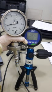
The pressure reading from the display of Fluke 754 is directly compared to the display or reading of the Unit Under Calibration (UUC) which is the pressure gauge. The Fluke 754 is a display side wherein the pressure module is the pressure sensor or transducer.
The pressure coming from the hand pump is converted to electrical signal by the pressure module then displayed by Fluke 754. Units and other parameters are also set here.
Reference Standard and Equipment:
-
Fluke FLUKE-754 Process Calibrator
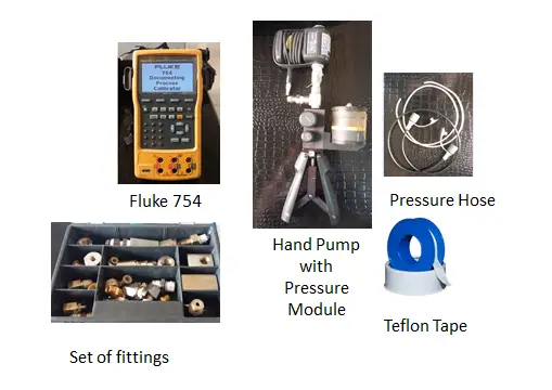
- Fluke 700P08 Pressure Module, 0 to 1000 psig
- Fluke 700HTP-2 Hydraulic Test Pump
- Thermohygrometer- to monitor temperature and humidity
- Set of fittings
- Teflon Tape
- Pressure Hose
- Set of wrenches
- Cleaning materials
- holder
Procedure:
- Inspect the UUC visually for any signs of damage ( pointer, threads, etc), readability of display, and cleanliness. Check batteries for digital pressure gauges and do an initial power-on test. Record observations on the sample data sheet below.
- Connect the pressure gauge to the pressure hose of the pressure module, If a holder is not available, hold the pressure gauge in an upright or vertical position. See to it that there is no leakage.
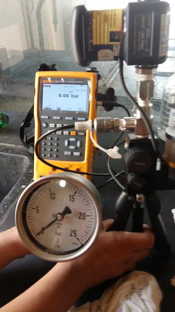
Fluke 754 and pressure module + Hand pump set-up - Position the hydraulic pump at the same level as the UUC. Close the Bleeder
knob of the hand pump (turn clockwise – see figure).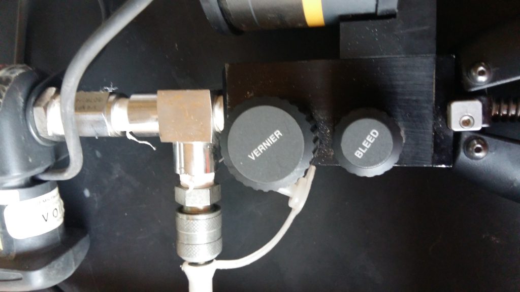
Pressure pump bleeder knob to control pressure precisely - Push the hand pump to apply pressure then check the display on the Fluke 754. Control the pressure properly to prevent damage to the pressure gauge.
- Take note of the measured value on the UUC. For analog gauges, Tap the face of the gauge every time you take a reading. To display the exact value, slowly turn the vernier knob of the hand pump (figure top left).
- Record five test points (increasing and decreasing) that are uniformly distributed over the range of the pressure gauge. You can follow the major scales but preferably 0%, 25%, 50% 75%, and 100% of the range. See and follow the data sheets below.
- For repeatability, repeat steps 5 to 8 twice (2x) until all required values are recorded on your data sheet.
- Calculate the tolerance limit by following the accuracy guide. Below is the accuracy class of analog pressure gauges based on the diameter of their faces.
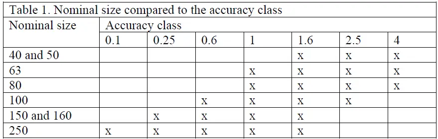
This means that if you have a pressure gauge with a 160 mm diameter with accuracy class of 0.25 (usually a test gauge), the accuracy is +/- 0.25% of its Full scale reading.
- A Full Scale reading of 250 psi has an accuracy of 0.625, (250 x 0.0025).
- So the limits should be 250+/-0.625. Above or beyond the limit should be investigated.
For a digital pressure gauge, accuracy are based on the manufacturer specifications.
10. Do necessary adjustments if the unit can be adjusted or repaired.
Visit related post here >>> 5 Techniques for adjusting a pressure gauge
11. If the readings are already within the specified limits, finalize records, put labels, and seal if necessary. End
The procedure above utilizes Fluke 754 as the display of pressure and the pressure module as the sensor. Another method is by using a Digital Test Guage just in case you do not have a Fluke 754. This has a simpler setup. Just connect the Test Gauge to the same hand pump and it is now ready to go. All controls are within the Test Gauge.
While the advantage of a simpler setup is provided by the Test Gauge, the range of pressure is limited, unlike Fluke 754, which has a set of pressure modules that can be changed and purchased to suit a wide pressure range needs plus other capabilities that you can do with Fluke 754. Also, pressure modules have a higher accuracy than a test gauge.
Click on below link to check on Amazon
- Fluke 700HTP-2 Hydraulic Test Pump
- Fluke 700P08 Pressure Module, 0 to 1000 psig
- Fluke FLUKE-754 Process Calibrator
Other Related Pressure Calibration Procedures
You may also find these related procedures useful:
- pressure gauge calibration using an electronic deadweight tester
- differential pressure gauge calibration
- differential pressure level gauge calibration setup
- pressure transmitter calibration
- pressure switch calibration
- pressure sensor calibration
- Pressure Safety Valve Calibration
- Pressure Gauge Adjustment and Repair
Frequently Asked Questions
How often should pressure gauges be calibrated?
Calibration intervals depend on the application, but many facilities perform calibration annually or based on instrument criticality.
What causes pressure gauge drift?
Drift may occur due to mechanical wear, vibration, temperature changes, or over-pressure events.
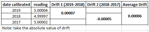
How to calculate drift in a pressure gauge?
Drift is the change in the output reading of instruments overtime at a specified period. It is simply the difference between the past result and the present result. See the example below: the readings are based on historical records, from its calibration certificate.
What tolerance is acceptable for pressure gauges?
The acceptable tolerance depends on the gauge specification and the requirements of the process being monitored. During calibration or verification, we normally use manufacturer’s specifications. Manufacturer’s specifications are mostly based on international standards, like ASTM or DKD.
What is hysteresis in a pressure gauge reading?
Hysteresis or hysteresis error is the error based on the difference between the applied increasing and decreasing pressure. Hysteresis = increasing – decreasing
example: pressure @ 10 psi increasing = 10.00; decreasing =9.95 psi
> hysteresis = 10.00-9.95 =0.05 psi
PRACTICAL IMPLEMENTATION
If you are performing in-house calibration:
You need:
👉Check out this ready-made pressure gauge calibration procedure package, which consists of a procedure, measurement uncertainty calculator, a datasheet, and a calibration certificate in one package. visit this link >>buymeacoffee.com/edsponce/e/312258
- uncertainty calculations
- standard procedures
- datasheets

Thank you for visiting, please do not hesitate to comment, share, and subscribe
Edwin
Leave a Reply