One of the most used temperature measuring and sensing tool is the thermocouple wire. Thermocouple usage is almost everywhere in a temperature measurement process.
It is mostly integrated on Temperature Controllers and Indicators as a sensor to detect temperature like on ovens, incubators, water heaters, thermo-hygrometers and other processes that require temperature monitoring.
It is also used as a probe on some thermometers used in meat or food thermometers and as a surface probe used in hot plates or hot surfaces. In this topic, I will present to you the different ways on how to calibrate or verify the accuracy of a thermocouple.
..
What is a Thermocouple Wire?
A thermocouple is a pair of two dissimilar metal wires connected together (welded or just twisted) at one end. The connection between these two dissimilar metals creates a reaction in which an electromotive force ( emf) is generated, a voltage source.
The generated voltage (emf) is proportional to the temperature where it is exposed to. A zero (0) mV corresponds to a Zero Temperature for a K Type thermocouples at Zero reference junction and increases with increasing temperature.
Since thermocouple wires create a voltage change every time it senses or detects the temperature difference, it is also called a thermocouple sensor.
Thermocouple wires have 2 junctions, these are:
- Hot Junction – this is the tip where the actual temperature measurement is sensed, the closed end. The part where we exposed to the temperature we want to measure.
. - Reference Junction (cold junction) – this is the part where we connect into the display or temperature controller, the open end. It is called a reference junction because this is the reference point used to attain a correct reading. Any temperature reading in this junction will be subtracted to the temperature reading from the hot junction. If there is no cold-junction compensation added in the circuit, you may think that it is reading incorrectly.
.
One solution for this is to create a cold-junction or an ice bath where the reference temperature will be exposed to zero temperature. Therefore any reading from the hot junction will be exactly the same as is because the effect of the reference junction will be compensated by the zero reference value.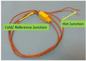
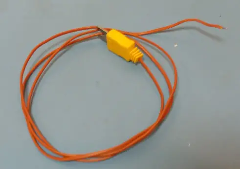
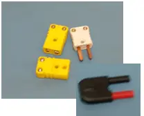
K-type Thermocouple wire Cold junction and Hot junction part
Most of the digital thermometer that we use today has a cold-junction compensation. Because of this, we do not need to worry regarding the effect of the reference junction in the temperature output because it is already compensated. You only need to worry about it if you are using a multimeter directly measuring a mV output. See no 3 below.
..
Types of Thermocouple Wires
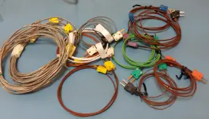
So many types of thermocouple wires are being manufactured mainly because each has its unique qualities, capability, and ranges depending on the suitability of the environment where they are used and exposed to. Below are some examples of commonly used thermocouple types with their ranges.
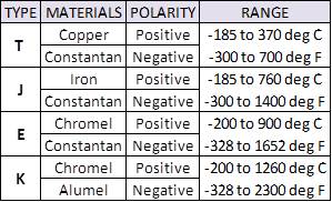
If you observe, K Type thermocouple wire has the widest range, therefore, it is the most used type of thermocouple wires.
.
Each type of thermocouple has its own unique characteristics which include:
- Diameter size or wire thickness
- Type of coating or insulation material
- Classifications – class 1 to class 3 thermocouples
.
This is why it is important to determine first your requirements before using any of them such as your user range, tolerance, and of course your budget.
.
Why Calibrate Thermocouple Wires?
To verify accuracy because of:
- Aging or decay
- Contamination by the working environment- make them brittle and shortens the life
- Oxidation in the environment when unprotected.
- Mechanical stress or breakage
..
3 Ways to Perform Thermocouple Verification
Since a thermocouple wire can be considered as a probe and a sensor connected to an indicator, there are more ways to have it calibrated or verified for accuracy. Just take note that a thermocouple wiring should be noted, it has a positive and negative polarity for it to function properly.
There is a plus and minus sign on its connector so this won’t be a problem if you check before you connect the wirings, also, it is color-coded, so make sure to check it before performing thermocouple wiring connections.
A good guide is to determine the polarity is to use the manufacturer’s specifications for color-coding. For a Type K thermocouple wiring, the yellow color is positive and the red color is negative. Also, considering the thermocouple connector or adaptor, the positive probe is thinner or smaller in width compared to the negative probe which is wider.
Below are the 3 ways to verify the accuracy of thermocouple and a calibration.set up:
.
1. Through actual temperature verification using a controlled temperature from metrology well and an indicator (Fluke 754 or Fluke 1524)
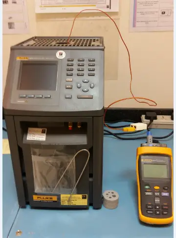
This is a set up using a Metrology Well ( fluke 9173) and an indicator ( Fluke 1524). The Unit Under Calibration (UUC) is the thermocouple. This is an actual verification of temperature where the thermocouple wire (probe) is soaked in the well and heat generated is read through the Fluke 1524 indicator.
This thermocouple calibration procedure or set up is used when the thermocouple wire has a welded end. This set up takes more time because you are using an actual temperature that requires stabilization on every temperature set point. Check the procedure in my other post in this link.
.
2. Through a simulated temperature which is an electrical signal generated Using a Fluke 5520A calibrator and an indicator ( Fluke 754 or Fluke 1524)
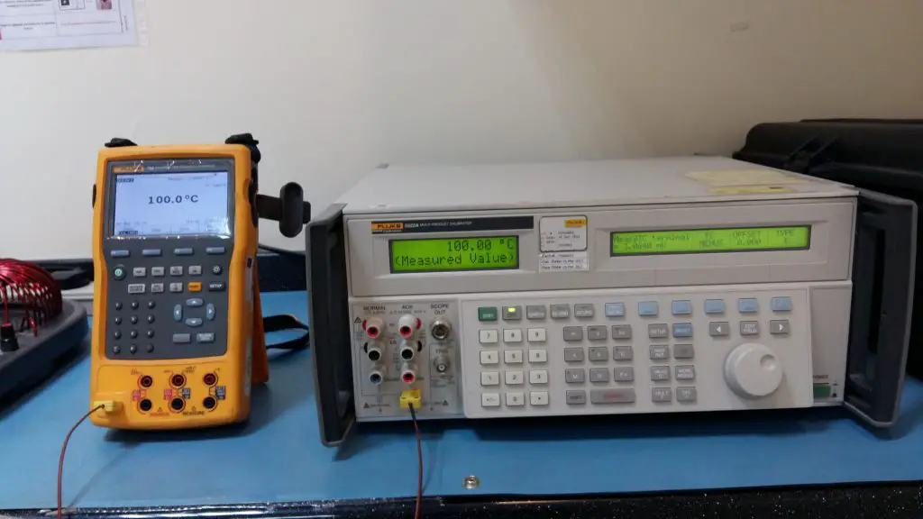
Another set up is through the use of a calibrator which is Fluke 5522a. This is a procedure where simulation is used to create the desired temperature.
The desired temperature can be simulated from the Fluke 5522A calibrator, you can select various types of thermocouples then the required temperature. By using an indicator ( Fluke 754 or equivalent indicator), we can display the temperature generated by the calibrator.
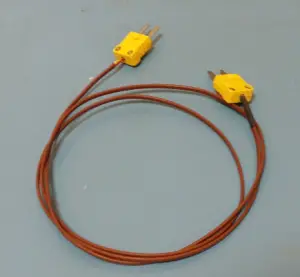 This set up is applicable to those thermocouple wires that have an open end connected to a male thermocouple connector or adaptor. This set up is more simple and takes less time to do compared to a thermocouple with welded end or junction
Check in this link the calibration procedure for this set-up.
..
.
..
3. Through a simulated output or input of a millivolt electrical signal Using a multimeter (Fluke 8846), 5522a calibrator or fluke 754
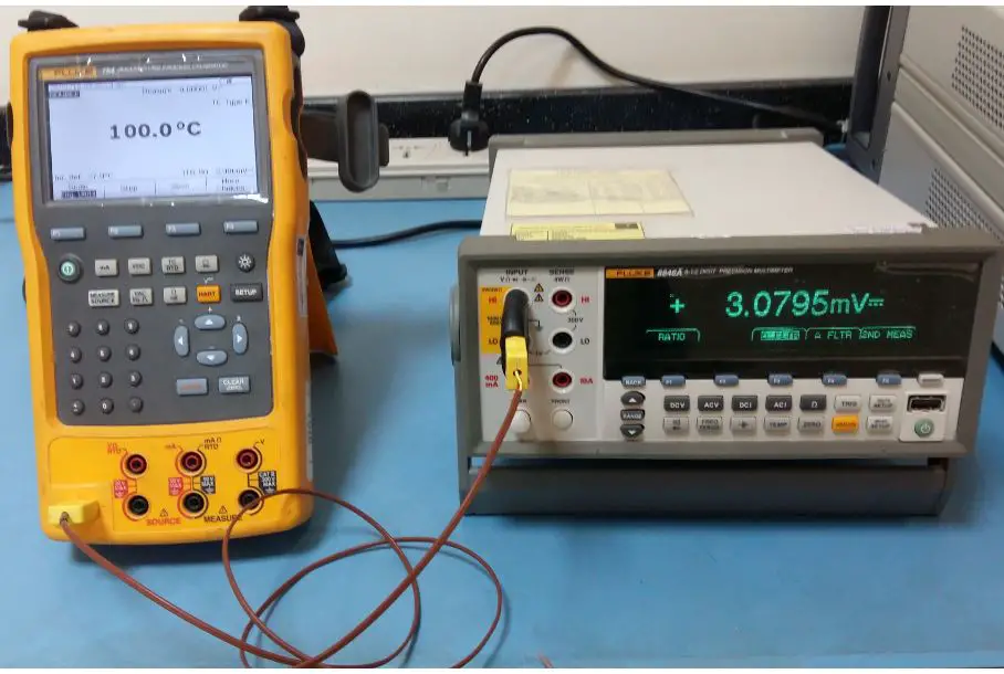
Now, we will use a multimeter as a display instead of a temperature or thermocouple indicator. The simulated signal will be generated also by Fluke 754 or Fluke 5522a calibrator. But instead of displaying a temperature readout, it will now be a voltage output (mV).
Just be sure to have the necessary thermocouple connectors or adaptors for it to be connected to the Multimeter (Fluke 8846 or any multimeter capable to display a millivolt readout to at least 3 resolutions) and take note again the polarity.
Since thermocouples can detect or produces an EMF during temperature differences, this emf or voltage generated can be measured in millivolts. Likewise, you can also generate a millivolt input and read it as a temperature output.
This is also applicable only to those thermocouples with open end junction with an adapter (unless you will cut a welded junction and perform this procedure and welded it back again once done).
In this setup, the problem we will encounter is the effect of the reference junction. The multimeter has no cold-junction compensation, therefore any ambient reading will have an effect on the measured or displayed value.
One solution is to soak the reference junction in a stable ambient environment where the temperature is measured with a separate thermometer. afterward, the reading in the thermometer will be converted to mV value then added to the displayed mV value of the multimeter. Then this is the time to convert and get the actual temperature value.
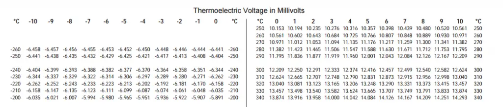
Depending on the type of thermocouple used, each generated temperature has an equivalent voltage in millivolt. By using a table that has been designed or computed, a temperature equivalent can be taken. Below is a sample table for a Type K thermocouple.
All of these Thermocouple Wire calibration Set Up can be carried out in any combination depending on your needs and availability of instruments or standards. Also, this set up is applicable when calibrating a temperature indicator or a controller in which the thermocouple is used as a probe or sensor.
For a detailed K Type thermocouple calibration, please visit this link: thermocouple wire calibration procedure-type k thermocouple.
For a list of thermocouple wires, you may click this link thermocouple wires.
Hope this thermocouple setup provides you additional knowledge, please feel free to comment for any clarification or feedback.
Thank you for visiting, please leave a comment, share, and join my mailing list.
Edwin
3 Responses
Henry Killingsworth
It stood out to me when you explained that the thermocouple wire is one of the most used temperature measuring tools. I would imagine that it would be important to make sure that a thermocouple is set up properly so that it can take proper measurements. If you need a thermocouple installed, it would probably be a good idea to hire a professional to do it for you.
Shubham Biradar
i just wanted to ask as when we calibrate a thermocouple in an actual heated well we may get an error upto to 2 degrees or more but when do with the method your are prescribing we get errors within 1 degrees so which is the correct method.
I think using actual heat is better for the calibration of Thermocouples. We calibrate a bundle of K type flexible thermocouple from both ends providing heat once at a time.
edsponce
Hi Shubam,
The method used depends on the tip of the thermocouple. If your thermocouple wire has a welded end, then you should use an actual heat. Calibration using a well is a little bit tricky, there are things that you need to consider in order to attain the most accurate results.
You should consider the following to avoid the additional error:
a. the depth of the well, thermocouple should touch the bottom of the well.
b. the width of the well, thermocouple should be properly fitted.
If you want to avoid these sources of errors, you may try a liquid bath or oven as the heat source.
I hope this helps, sorry for the late response.
Edwin