Do you want to make sure that the rpm reading of the tachometer that you are using is accurate?
In this article, I will share with you a simple and effective way on how to calibrate a Digital Tachometer, the Amprobe Tach20, a non-contact and contact type in one. But in this procedure, we will focus on the non-contact type, we will calibrate the tachometer using its laser pointer.
I will also share with you on how to verify the reading of your tachometer if it is within specifications or not.
If you already have a Fluke 754 Process Calibrator, then this is an additional capability and an added value because we will use it as our reference standard. This is another useful feature of Fluke 754.
For more details regarding its capabilities, visit this link
We will use a simulated signal (frequency) generated by Fluke 754 with the addition of a LED as the source of our reference value.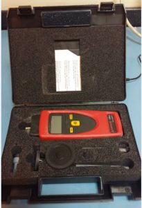
In this procedure, there are no adjustable parts so adjustment is not an option, we will verify only the accuracy of the handheld digital tachometer in a non-contact way.
First of all, let us define what a tachometer is and what does a tachometer measure?
A Tachometer is an instrument used to measure the speed of a rotating body. A shaft or a motor for example. The unit of measurement is in revolutions per minute (rpm), m/sec or ft/min.
Another useful application of a tachometer is to measure length or distance. It has a unit of ft, meters, or yard,
There is a tachometer installed in a car that measures its speed and it is mostly known as the speedometer. The tachometer that I will introduce here is the Handheld Digital Tachometer that is commonly used in industries that measure the speed of a rotating body or a shaft in a motor or simply a fan.
It is a handheld type that you can carry anywhere and used via its laser pointer as a non-contact or through its nozzle (with accessories) as a contact measurement. This is the Amprobe Tach20 Digital Hand-held Tachometer.
How to Use a Non-Contact Tachometer (Amprobe Tach20)?
You can use a Tachometer either contact or non-contact depending on the setup and convenience on how you can measure a rotating body.
It is very simple to use, For a non-contact measurement, just point or aim the laser of the tachometer on a rotating shaft with a reflective tape stick to it. Ensure a steady hand while aiming to get an accurate reading.
Ensure the distance from the measured part is not more than 24 inches for accurate measurements.
Another is by directly touching the rotating body for a contact measurement, accessories are used for a different type of surface (provided in the set).
The Amprobe Tach20 is a user-friendly, only 3 buttons are used to fully operate the instrument. Just press and measure.
The Principle of operation behind the non-contact type tachometer is that it has a sensor that senses the fluctuation of light or the switching off/on of a light source or a changing color (a reflection of white and dark color) while a body is oscillating or rotating.
This fluctuation or oscillation has a corresponding frequency in which converted to speed and displayed as RPM. In this setup, the light in the LED is generated by an oscillating sinewave with the corresponding frequency.
Below is a conversion of Frequency (Hz) to Revolutions Per Minute (RPM).( visit WIKI for more explanation)
1 Hz = 60 RPM
For the 60 Hz above, expect the output to be 3600 RPM (60×60).
Why do we need to calibrate A tachometer?
A tachometer is used to verify the speed of a rotating motor that produces a specific product or monitors a specific process. By achieving the desired speed, quality and safety are achieved.
Every motor has moving parts that are exposed to wear and tear and therefore needs to be monitored constantly. Also, since most are operated today electronically, we cannot remove the effect of drift and other environmental pressures (temperature, dust, vibrations, etc).
Tachometer Calibration Procedure
The video below is a simple demonstration of tachometer calibration using an Extech tachometer and an Amprobe digital hand-held tachometer non-contact type.
This RPM calibration procedure is simple to do. I am using the model Tach20 from Amprobe but this is applicable to all tachometers with a non-contact capability using a laser pointer (optical sensor).
Observe the following before calibration:
- Be sure to check first the functionality of the tachometer (power on, good battery, good physical condition, clean…).
- Stabilize the instruments to a suitable environment condition ( monitor temperature and humidity) – check this link for more info regarding temperature and humidity.
- Warm up the reference standard by powering on for at least 30 mins. before using to ensure stable functionality ( good performance)
- Prepare your Measurement Data Sheet (MDS) to record necessary details of the Amprobe Tach20 Tachometer (brand, model, serial, etc)
Tachometer Calibration Standard
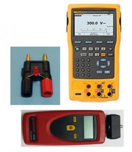
The equipment we need is:
- Fluke 754 Process calibrator
- A piece of LED (normal 5mm LED)
- A connecting wire or connector.
Calibration Set up:
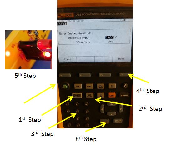
- Power on Fluke 754, select the source function
- Press the Frequency/Hz button.
- Set the voltage to 2V and Set the Waveform to a square wave
- Press done.
- Connect the LED using the connector provided in the port under source (see pic). (a pair of connecting probes can be used also).
- Press frequency ( Hz) button ( same as the 2nd step button)
- Set the required frequency range (an example is 60 Hz)
- Press enter
.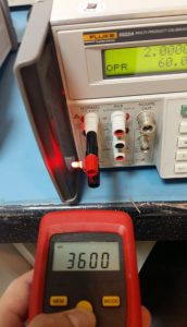
You can use any LED that is powered by an acceptable voltage with a known Frequency. In this pict, I use a Fluke 5522A process calibrator to simulate the frequency and voltage. Handheld Tachometer Calibration Procedure:
- At this stage, the LED has lighted, Focus the handheld tachometer on the blinking LED with a distance of 3 to 5 inches (until 24 inches) Ensure stable aiming of the light to get the most accurate reading.
- Wait until the reading has stabilized then record. (perform at least 3 trials)
- Change the frequency range then repeat steps 6 to 9 until the required set points are reached.
- Complete your MDS record
- End of calibration
How to Perform Tachometer Verification?
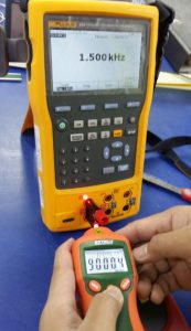
What we need during tachometer verification is the specification of the tachometer or the user tolerance. This is our basis to decide whether the tachometer will pass or fail the verification.
Below is an example:
as per specification, the Amprobe Tach 20 tachometer has an accuracy = 0.02% of reading.
tachometer expected reading = 60 000 rpm
tachometer actual reading = 59998
- determine the accuracy value in rpm: 0.02/100*60000 = 12 rpm.
- and now the tolerance is +/- 12 rpm,
- therefore, the verification result is PASSED as per the actual reading of 59998.
Conclusion
There you go, I have presented and discussed what a tachometer is, including the setup and procedure for calibrating a Digital Handheld Tachometer using a Fluke 754 with a piece of Light Emitting Diode (LED). The procedure is so simple that you can do this anytime you want to verify the accuracy of your tachometer.
I also included the procedure on how to verify the accuracy of the tachometer and determine if the reading is pass or failed.
Ensure that Fluke 754 is calibrated in order to have a reliable and traceable calibration. Verify the calibration status of your reference standards by reviewing its calibration certificate. How to properly review a calibration certificate? Visit this post, click here
To view it in Amazon, click here Amprobe TACH-20 Tachometer with Contact and Non-Contact Measurement
Thank you for visiting my site, please leave a comment then subscribe on my mailing list.
Edwin
34 Responses
John Price
Can you provide the specifications on the LED light that was used?
This is something that I would like to do in our Metrology Lab but the choices of LED’s are endless.
edsponce
Hi Mr. John,
Appreciate your comment. I only used a normal 5mm LED. you can check the specs in this link. https://www.sparkfun.com/products/9590
I would be happy to hear if it will work perfectly for you.
Thanks and regards,
Edwin
ABu Yazid
Good Reference
edsponce
Hi Mr. Abu,
I appreciate your comment. Thank you for reading my post.
Best regards,
Edwin
Ricardo Vilmenay
Hi Edwin,
Great article. It’s help me a lot to create an in-house calibration setup for all the laser tachometers that I usually sent out to an external lab for certifications.
edsponce
Hi Mr. Ricardo,
I am glad that my article has helped you in some way and thank you for sharing the experience. Just make sure that your reference standard is calibrated to have a traceable calibration.
Thank you for visiting my site.
Best Regards,
Edwin
febriana winda yanti
Hello, sir. I want to ask. What reference do you use to calibrate the tachometer using the Fluke 754? can I get the reference? Thx
edsponce
Hi Febriana,
We are measuring a frequency parameter and therefore, You can use Euramet cg.15 as the reference.
Thanks for visiting my site.
Best Regards,
Edwin
febriana winda yanti
Thank a lot Sir🙏
edsponce
You are welcome Madam.
Jose
Hi Edwin,
Great work. Thank you for sharing.
I would like to know if there is any electrical parameter to get in mind when we try to do something like this. I mean, for example LED current consumption.
Regards,
edsponce
Hello Jose,
You are welcome. Thank you for reading my post.
Yes there is, the two most important parameter is the voltage and the frequency waveform, we should ensure that the voltage is within the specifications of the LED in order to function normally and provide the desired result. For the frequency, some LED does not function in a squarewave output setting but will function in a sinewave.
I hope this helps,
Edwin
Esther Zimmerman
Hello,
Kindly provide us your best price for the following item;
Enerpac Hydraulic Pump -10,000psi———-40 pieces
Looking forward to doing business with your company
Thank you.
Sincerely yours,
Esther Zimmerman
Director, Purchase & Strategic Sourcing
CVS Health Corporation
One CVS Drive
Woonsocket, Rhode Island 02895
edsponce
Hi Esther,
Thank you for the inquiry, but sorry to inform you that I do not supply such items. This is just an educational website.
Thank you for visiting my site.
Best regards,
Edwin
Zack
Can we use this method to apply 17025 accredited calibration in our scope?
edsponce
Hi Zack,
Yes, you can, this will fall under electrical parameters specifically frequency. You just need to validate your procedure before using it.
Thanks for reading my post.
Best Regards,
Edwin
Poer
Thankyou for this article, but how about to calibration of: Pulse engine Tachometer? Ex: OPPAMA PET 2000DXR.
Thanks for your answer
edsponce
Hi Poer,
You are welcome, thank you for reading my posts. Sorry to inform you, but I did not yet encounter a pulse engine tachometer so I have no idea about it. The main principle of the tachometer I shared is based on a frequency either of a spinning body or a blinking light.
If there is a spinning part in the engine related to the cylinder movement, you may try to use another non-contact tachometer which is calibrated then compare it with the display of the pulse engine tachometer, I believe it will work.
Thanks and regards,
Edwin
iron works
I blog often and I seriously thank you for your content. This article has really
peaked my interest. I’m going to bookmark your blog and keep checking for
new details about once a week. I subscribed to your
RSS feed too.
edsponce
Thank you Britt.
Hashir Iqbal
Hi Sir,
I hope you are doing well, could you please tell me how to calibrate the DMM without using Fluke and how to calibrate the sound level meter, thickness coating gauge and tachometer in an easy way ?
Regards,
edsponce
Hi Hashir,
There is no easy way in calibration, only the right way. It is based on the setup and the reference standard you are using. But I believe what I have shared here about the digital tachometer is the easy way. Once you have become familiar with the execution of the calibration procedure, it will become easy in the long run.
In DMM calibration, there are other multiproduct calibrator that you can use as long as it meets the requirements of the insturments or the user. You can check Yokogawa models. For coating thickness gauge, it depends on the model, usually you can use a ‘calibration foil’ for electromagnet or eddy current based sensors.
I hope this helps.
Edwin
BoonGuan
Hi Sir,
Great article, how you calculate the source of uncertainty for this calibraiton
edsponce
Hi BoonGuan,
The sources of uncertainty can be calculated based on the frequency of the calibrator. Convert all parameters to rpm then you can now calculate its measurement uncertainty.
I hope this helps, thanks for reading my post.
Edwin
Fred K
Interesting article. I am wondering if there is a way to use a non contact tachometer to measure door closing speed. My thought is to use a piece of vinyl magnetic strip with a series of the reflective material evenly spaced, placed on a sliding door of a van, and hold the meter while the door is closed. Would this work, and how difficult would the math be to accurately gauge the door closing speed?
edsponce
Hi Fred,
I do not have an idea for the math when it comes to a linear motion for a tachometer, because the unit is RPM which is for a rotating body. If there is a rotating parts where you can put your reflective material while the door is closing, I believe it would be more easy and appropriate.
Thanks for visiting my site.
Edwin
Daniela Rivera
Hi Edwin,
Thanks for your information, it helped me a lot. Do you know a way to do that measure without use the fluke as a reference for frequency? I mean it would be to do the convertion from rpm of the indication of the tachometer to Hz?
Greetings from Mexico.
edsponce
Hi Daniela,
You are welcome. The method I share is an electrical stimulation. The sensor of the tachometer is triggered by the blinking light, I did not try it yet but if you have a motorize fun with known rpm, maybe it could work.
Best regards,
Edwin
Gabriel
Thanks so much. Very useful write-up
edsponce
Hi Gabriel,
You’re welcome. Thanks as well for visiting my site.
Best regards,
Edwin
Mohammad Aun
Hi Edwin
currently i am following your all blogs. can you give uncertainty calculation example for Tachometer .
Regards
edsponce
Hi Mohammad,
May I first ask if you already know or had an understanding of how to calculate measurement uncertainty? because if you know, I can just show you the uncertainty budget.
Thanks for reading my blog posts.
Aun
very informative article, can you present Uncertainty calculation for the same?
anwar sanusi
Thanks so much. Good Article…inspiring