As a Technician whether working as a maintenance or in electronics repair field, multimeters is the most used tool to test, diagnose, monitoring, and repair. Your decisions are based on the data that you have taken or on the output that the multimeter is displaying.
Regardless of the usage, the multimeters should be highly reliable for us to provide a highly accurate diagnosis or decisions on every testing that we are doing. So the importance of multimeter calibration should not be taken for granted.
In this post, I will present a multimeter calibration procedure, specifically the Fluke 87 multimeter, which is calibrated using a multi-product calibrator known as Fluke 5522A. This procedure is also applicable to other types of multimeter.
How do we know it is calibrated?
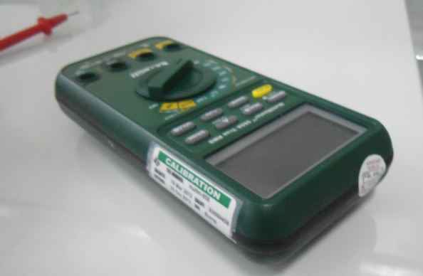
We can determine if the multimeter that we are using is calibrated by looking or checking if it has a calibration label stick to it. It contains the calibration date and due date of the instrument. (see image).
Furthermore, if it has a label on it, there should also be a calibration certificate that contains all the details about the instrument plus the calibration results and any limitations that have been observed.
Fluke 87 V Digital Multimeter is one of the best multimeters today. As a simple review, it has a higher accuracy, wider frequency range and higher resolution compared to others.
What makes it more useful is that it has a built-in temperature measurement ( just do not forget to include the thermocouple probe and connector in the set). Almost all the measuring capabilities are added in one package.
As a calibration technician, utilizing this kind of measuring device is a good investment and a big help on your troubleshooting environment. But having the knowledge to verify its accuracy is also a big plus because you are not just making an accurate measurement but also a reliable measurement. You will have a higher confidence in the performance of your multimeter.
How to Calibrate a Digital Multimeter?
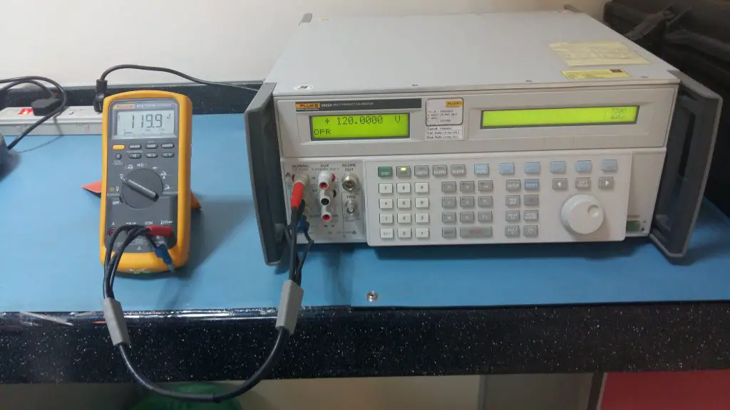
Based on Fluke 87 V Specifications, below is a verification/calibration method using a Fluke 5522A Multiproduct calibrator. Verification of multimeters are simple, you just need to have a reference standard where you can compare your reading and preferably more accurate than the multimeter (preferably 4:1 accuracy).
Fluke 5522A provides this requirement. The connections are also simple, if you know how to use the multimeter during testing, the connections are the same while using the Fluke 5522A calibrator.
The only difference is the current connection, usually, current is connected in series with the load, in using Fluke 5522A, it is directly connected in the port of Fluke 5522A, which makes it very simple.
Objective:
To define calibration procedures for Fluke 87-V Digital Multimeter. This procedure is also applicable to other types of multimeter. You just need to check the specifications in order to determine the test points.
Calibration Method:
The reading of the Fluke 87 V multimeter is compared by the electrical signal generated from fluke 5522A Multi Product Calibrator. The Multi Product Calibrator can simulate almost all the required signal needed to verify the accuracy of Fluke 87 multimeter. This procedure is applicable almost to all multimeters whether analog or digital.
Requirements:
- Warm-up time: At least 1 hour for proper stabilization
Temperature: 23 +/- 5 deg C
Reference Standard and Equipment:
- Fluke 5522A Calibrator
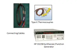
- HP 3325B Synthesizer/Function Generator (optional, this is needed if the frequency range that you want to verify is very high)
- Extech RH520A Humidity and Temperature Chart Recorder with RS-232 Computer Interface
- Connecting cables
- Type-K Thermocouple
Procedure:
- Allow the temperature of the calibrator and Unit Under Calibration (UUC) to stabilize at room temperature.
- Check the battery and fuse, replace if necessary.
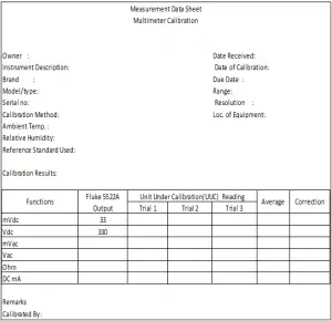
- Record necessary details on the Measurement Data Sheet (MDS)( Brand, Model, Serial, etc.)
- Check for any physical or functional defect, discontinue calibration if defects are noted. Inform the owner immediately.
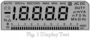
5. Display Test:
5.1. Turn the Unit Under Calibration (UUC) on while holding down the AutoHOLD button to view all segments of the display. Compare the display with the appropriate example in Figure 1.
6. AC/DC Voltage Verification:
6.1 Connect the UUC to the 5522A calibrator as shown below.
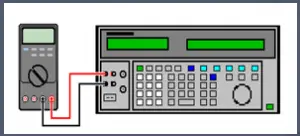
6.2 Position the rotary switch of the UUC to the desired voltage range function.
6.3 Position knob for AC voltage measurements for all ranges,DC Voltage measurements from 4 V to 1000 V ranges and 400mV range.
6.4 Set the 5522A calibrator to each of the required voltage set-point values shown in Table 1 and take note of the measured values on the multimeter. Record values on the MDS
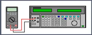
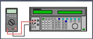
7. AC/DC Current Verification:
7.1 For current measurements between 4mA and 400mA, make connections shown on Fig. 2. For currents above 400mA, make connections shown on figure 4.
Current settings in multimeters have separate ports. Low current range have separate ports with the high current range. So be aware of the proper settings and connections of probes.
Make sure to follow the correct connection and settings for this procedure, a mistake in connection can damage the unit. usually, fuse are getting blown in this stage if connections are not followed properly.
7.2 Position the rotary switch of the UUC to the desired current range function.
7.3 Press the blue button to select AC or DC mode.
7.4 Set the 5522A calibrator to each of the required current set point values shown in Table 1 and take note of the measured values on the multimeter. Record values on the MDS
8. Resistance/ Capacitance/ Diode Verification:
8.1 Make the same connections shown in Fig. 2
8.2 Position the rotary switch of the UUT to resistance/ capacitance/ diode range.
8.3 Set the 5522A calibrator to each of the required resistance values shown in Table 1 and take note of the measured values on the multimeter. Record values on the MDS
9. Fluke 87 V Temperature Verification: We will use a thermocouple here.
9.1 Connect the UUC to the 5522A calibrator using a Type-K thermocouple. (VΩ terminal and COM terminal of the UUT to the thermocouple port of the 5522A calibrator.)
9.2 Position the rotary switch of the UUC to temperature range.
9.3 Set the 5522A calibrator to the required temperature settings and take note of the measured values on the multimeter display. Record values on the MDS
How to determine the Temperature Verification Tolerance?
Based on the specifications of Fluke 87V in its manual, the accuracy of temperature which includes the type K probe is 2.2 Deg C or 2% of reading which ever is geater ( -40 to 260 deg C). For example, at 100 deg C the reading should be within 97.8 to 102.2 Deg C.
10. Frequency Verification:
10.1 Connect the VΩ and COM terminals of the UUT to the 3325B calibrator Signal Output using a BNC cable and BNC to dual banana adapter.
10.2 Position the UUC rotary switch to AC Volts then push the HZ% button for Frequency function.
10.3 Set the 3325B calibrator to each of the required frequency setpoint values shown in Table 1 and take note of the measured values on the multimeter. Record values on the MDS
11. Turn the UUC off, disconnect all cables and secure all connections.
12. If the readings are within the given limits, update the record, do labeling and sealing.
Table 1. Performance Verification Test limits
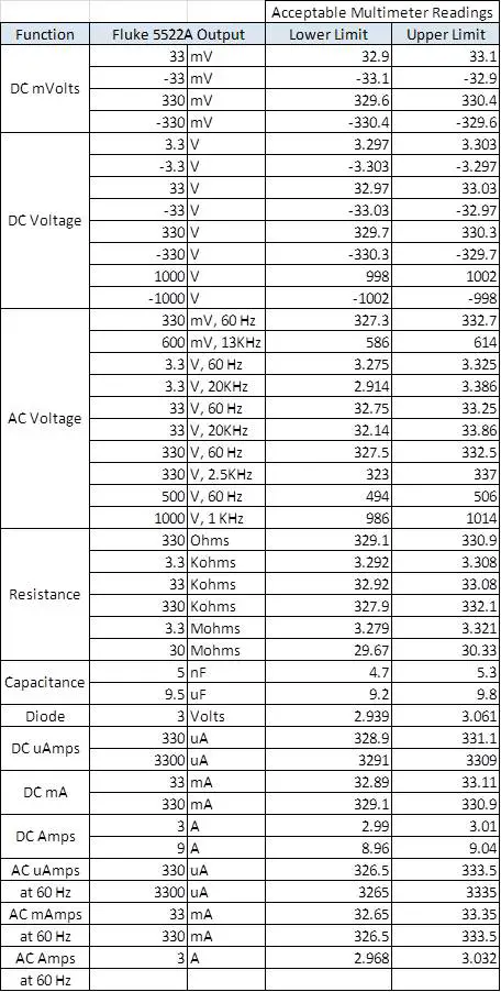
Click table to enlarge
End of Verification
Multimeter calibration requires a knowledge of basic electronics in order to understand its functions. Calibration is simple if you have this background. Based on the procedure presented, calibrating a multimeter is just like using it, measuring a device (for example a resistor). The only difference is that you know the value to be tested therefore you can verify its accuracy through comparison.
For a list of multimeters please click here.
Thank you for visiting my site, please comment, share and subscribe
Edwin
15 Responses
Paul Brubaker
Hi Edwin,
I need some advice… most of the calibrations and inspections I perform are dimensional, however our business has a dozen multimeters and other relatively low accuracy electronic devices requiring calibration. I am In the market for a multifunction calibrator and have found excellent products from both Fluke and Hewlett-Packard. The only problem is that they both cost more than my house, and can not be justified in our small business. Can you recommend any off-brand multifunction calibrators that only provide more basic functions that don’t cost as much as a Ferrari? Any suggestions would be welcome! Have a great day!
edsponce
Dear Mr. Paul,
Good Day!
These are my recommendations:
a.You can assess if the multimeters have a critical contribution to the quality of your products. If you are only using it as a reference, just say, to detect the presence and value of a voltage or current, but is not necessarily a having a direct effect on the manufactured products, you can label it as calibration -not- required or for reference only. But is should be properly documented. You can check my related post in this link
b.If it is not that critical in usage and since the multimeters you are using are relatively low accuracy, have one unit/ pc of multimeter calibrated, preferably with the highest accuracy and use it to calibrate other multimeters. You can make a direct comparison every time you use it with the other multimeters. This method is a “limited calibration”, but just in case it is acceptable in your process, you can implement it.
c.I have found a standard that was introduced to me just within this year, I believe this is far cheaper than Fluke (or a Ferrari ツ)..Please check this model under Yokogawa. 2553A DC Calibrator and 2558A AC voltage current standard. They can be purchased separately.
Hope this helps,
Edwin
Majid
is this calibration instrument just for FLUKE instrument test or all other instrument tests
edsponce
Hi Mr. Majid,
Thank you for reading my post. The procedure presented here is for all handheld multimeters including most precision multimeters.
Best regards,
Edwin
Andy
Hello! can we adjust the read value of the fluke 87 DMM if ever the reading is far offset than the reference? How do you proceed with such cases if ever the accuracy error is really big.
edsponce
Hi Andy,
Yes you can adjust. when you open the DMM, you can see inside a variable capacitor and a potentiometer that you can rotate to adjust to your desired output.
I am not fully familiar with the adjustment because it is very rare that I encounter such DMM with large offset so my knowledge in adjustment is limited. This now will fall under the repair side. But in any case, you can download the service manual in this below link and follow the instructions. .. http://assets.fluke.com/manuals/83_85_87smeng0500.pdf
But be sure to have a reference standard or a calibrator to verify the correct output.
Hope this helps.
Thank you for visiting my site. Appreaciate if you can update me back if you have successfuly adjusted your DMM.
Edwin.
Manar
Hi Edwin
Could you recommend another calibrator to calibrate multimeters and clamp ampere but with much cheaper value .
edsponce
Hi Manar,
I only tried Fluke calibrators for multimeters and clamp meters but you may check this from YOKOGAWA, 2553A DC Calibrator and 2558A AC voltage current standard. They can be purchased separately. You still need the current coil for clamp meters.
Hope this helps.
Best regards,
Edwin
Sergey
Hi Edwin.
Tell us how you measured and calculated the uncertainty. Accurately for 1 value, for example 1 V. You took a series of measurements, for example 5 and chose the worst one, and then calculated the uncertainty by type A. Then by type B.
Or is it enough to take 1 measurement and record it in the protocol, and then press another 5-10 measurements to calculate the uncertainty by type A?
edsponce
Hi Sergey,
Measurement calculation has more processes to consider. You need training to understand the calculation.
It is the combined effect of TYPE A and TYPE B using the RSS Method.
Regarding Measurement uncertainties for a DMM or multimeter, the main components that I used are:
1. Type A: repeatability, for example, 5 repeated readings
2. Type B:
a. The specifications of the standards from its manual (accuracy or 1-year specifications)
b. The measurement uncertainty of the standard from calibration certificate
c. The Drift of the standard
d. The resolution of the std
e. The resolution of the UUT
I hope this helps,
Edwin
Kevin
How can we calibrate a fluke multimeter without calibrator? I mean is there another way for it.
edsponce
Hi Kevin,
For a Full calibration, we need a calibrator, but for partial calibration, you can use another calibrated multimeter then compare their readings from any capable and available electrical signal.
Thanks for visiting my site.
Edwin
Awais
I don’t have a favorable opinion of the Fluke 5522A as it tends to be quite slow in my experience. In comparison, I find the Wavetek 9100 to be significantly superior to the 5522A, despite the fact that the 9100 is an older model. Interestingly, I had a defective Wavetek 9100, but I managed to repair it on my own.
Martin
This is actually not a calibration, but just a determination of the error. For calibration, the unit needs to be taken apart and depending on the model and brand, there is an adjustment inside, or you need to hook up a computer to program the correction values. I was looking for exactly this information, since my 87V is 0.28mV off track on 6V and I need to get this corrected
edsponce
Hi Martin,
Calibration means in a simple understanding is the comparison of the UUT with the Reference standard to determine the “error” or in other terms, the “accuracy”. The comparison performed that determines the error and measurement uncertainty is the main point in calibration. If the error encountered is not acceptable, you have the choice to perform an adjustment if capable or just use a correction factor from its calibration certificate.
If you have the necessary equipment, the adjustment procedure, together with the calibration procedure is available through its manual.
I hope this helps,
Edwin