Hello guys. I will share today this calibration set up that I just finished earlier. The calibration of a furnace. Maybe some of us are not familiar what a furnace is, a furnace is a temperature enclosure almost the same as the oven but operates at a much higher temperature usually reaching 1200 Degree Celsius. It has a much thicker insulation than the oven and therefore has a smaller space inside. Don’t try to carry it by yourself just in case because it is very heavy( full of ceramic insulators or bricks).
Why do we need to calibrate a Furnace?
The furnace has a temperature indicator or a controller that utilizes an electrical signal ( mV) coming from a temperature sensor (a thermocouple). This thermocouple inserted inside the furnace has a probe with special insulation or coating. Due to high temperature, this probe oxidizes and reacts to other elements and soon becomes an additional coating that reduces that efficiency of sensing, sometimes a crack is being generated. Because of this, its accuracy is affected and we can only determine this through calibration.
Depending on the type and design of a furnace, calibration is almost the same. It has a temperature controller and a thermocouple ( or an RTD) as its sensing element.
Furnace Calibration Setup
There are 2 ways in which we can set up a calibration method for a furnace, one is through direct simulation of a signal to its indicator and the second is through actual temperature measurement.
The first set up is through a direct simulation of a signal.
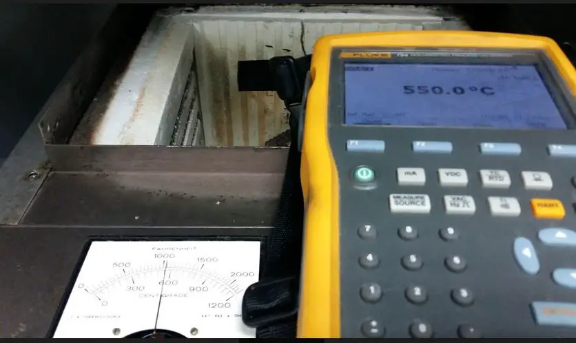
Furnace calibration is very simple in this method, verification is exactly the same as with the temperature controllers. We will use a Fluke 754 and a thermocouple as our reference standard. The furnace that I just calibrated has an analog display and using a Type k thermocouple wire as its sensing element.
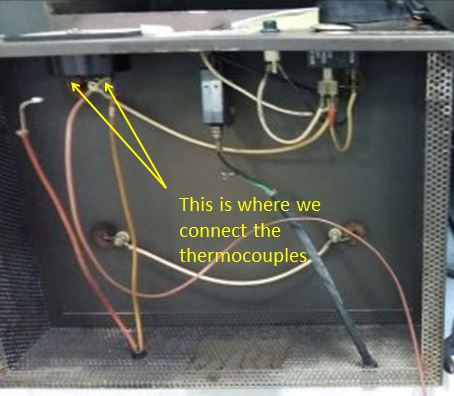
Based on the figure, just access the indicator directly, replace the attached thermocouple of the furnace with my thermocouple connected to Fluke 754 Process Calibrator.
This is the difficult part that I encounter in this present procedure. I need to remove most of the screws and access the temperature indicator at the bottom. Afterward, the furnace must be tilted laying on its back.
Connect the thermocouple at the indicator then set Fluke 754 to the desired thermocouple type to simulate the required temperature. You can verify the full range in this method easily and fast.
This indicator that I just verified has an error so an adjustment is required. The temperature indicator has a needle with a screw in the middle in which you can turn for adjustments ( be careful in this part because the screw with the pointer is very sensitive).
This method of furnace calibration as we observe is only verifying the accuracy of the controller but not the whole furnace itself because the signal is not coming from the furnace but from the calibrator, and therefore we need the second method below.
The second set up or method for verification is through actual measurement of the temperature inside the furnace.
This method will verify the actual temperature generated by the furnace.
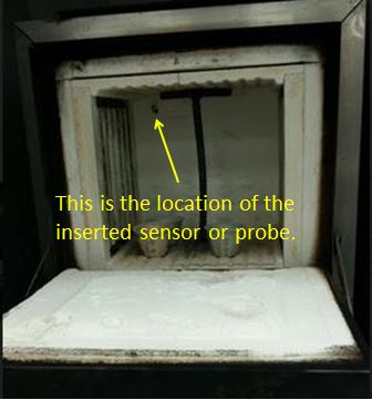
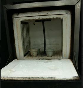
In order to take an actual temperature inside a furnace, we need to insert a thermocouple. Once open, you can see the sensor or probe of the furnace immediately, this is inserted from the back which is connected all the way to the indicator of the furnace.
We will put our inserted thermocouple in the exact location or position of the probe to have a more accurate response and reading in comparison with the probe of the furnace.
We need to operate the furnace to its user set point. This method will take up more time because we need to stabilize the temperature inside (it takes me around 30 mins in one set point only). Once stabilized, record the reading and compare results.
There are other methods to be included in this procedure, if the uniformity of heat distribution is critical in your process, we can do a temperature mapping, where we will use at least 5 pcs of thermocouple wires and distribute it inside the furnace. In this way, we can determine where is the location that has least or more amount of heat being delivered.
But for this post, I only use a single thermocouple but directly placed together inside with the sensor of the furnace. There is a whole above the furnace where you can insert a thermocouple.
As you can see, furnace calibration is not that difficult. One important thing to consider is to know how to access the indicator and use the exact type of thermocouple. Depending on your procedure and usage of the furnace, an actual measurement of temperature is the best and is mostly enough to determine the accuracy of the whole furnace.
To see the procedure on how to calibrate a temperature controller, please visit this link
To know more about the capabilities of Fluke 754, just click here
Thank you for visiting my site, please leave a comment and subscribe.
Edwin
4 Responses
Fernando
We perform furnace calibration putting a long TC calibrated as a standard to reach the middle point of the furnace. By this way we ensure the temperature in this point and deliver either what you have to select in the controller to meet certain temperature at this point or “if “you select in the controller you have in the middle…
Best regards.
edsponce
Hi Fernando,
Yes you are right. You can also include one more piece of thermocouple wire to be installed near the sensor of your furnace (if the sensor is not in the center) to have a better comparison on the temperature that your furnace is generating. If you want to get the uniformity of temperature inside your furnace, 3 thermocouples are better, but still, it depends on the size of your furnace.
Appreciate your comments,
Best regards,
edwin
Felix
Hi Fernando,
How do you place the sensors at the furnace to the intended locations?
edsponce
Hi Felix,
you can position it on its rack or you can use thermal tape or heat-resistant tape to position them in their intended locations.
I hope this helps,
Edwin