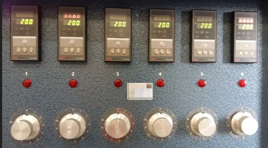
Equipment that is using temperature in its process can be found in almost all industries. Almost all these temperature generating equipment have a Temperature Controller installed in them and mostly these are digital temperature controllers.
The temperature controller is not a stand-alone device, it is integrated as a part of a system. They are mostly found on equipment like ovens, incubators, sealers or packaging machines, heaters, dryers, and much more.
Temperature controllers make temperature very stable because of its feedback mechanism in a closed loop circuit. One part is sensing the input while the other part is controlling the output to match the temperature setting.
A temperature controller in order to control a certain temperature needs a sensor, most commonly used sensors are thermocouple wires and RTD. This is one of the best characteristics of a temperature controller, it can be connected to different types of thermocouple or RTD depending on the range and environment where they are installed. It is also an indicator because it has its own display.
When it comes to operation, some are user-friendly which is easy to navigate and connect the input supply while others are very complicated where a user manual is needed to in order to access and operate it.
So as a reminder, always seek first the user manual before operating or making some calibrations, there are so many types of brands or manufacturers of a certain temperature controller and having its manual a priority saves time.
5 Ways to calibrate a temperature Controller
There are more ways that a Temperature Controller can be calibrated, below are some that I use:
- The first method is by temperature simulation (from a calibrator like Fluke 754 and a thermocouple wire) where a temperature source is an electrical signal. (see procedure below)
- The second method is through actual temperature by the use of a bath, either dry or wet bath (commonly used is a dry well) where the sensor is dipped in the hole of a well. (see procedure below)
- The third is by comparing its reading to a more accurate thermometer or temperature indicator with a separate sensor. In this method, the sensors are clamped, inserted, or fastened by screws into the heat source or heating element. This method is applicable when the sensor or the controller back panel is not accessible. This can be seen in hot surfaces or hot plates. (see sample setup below)
- The Fourth is a simulated voltage (in mV), resistance (for RTD) and current like the 4-20 mA depending on the settings or programming of the temperature controller. (mostly related to method 1)
- The 5th is by measuring the temperature directly inside an enclosed system using a separate sensor and indicator then comparing its display with the temperature controller. This is usually applied to most ovens or furnace. See this link Ovens
Of course, the easiest is the first one and it is the most commonly used technique. Mostly, the calibration of temperature controllers is a closed loop system, means that you are calibrating a group, not just a controller.
Since a controller needs an input in order to control an output, calibration of both input sensor and its display is already a closed loop calibration, assuming that the sensor used, whether a thermocouple or RTD is permanently connected and used during the calibration process.
As per Experience…
One good thing about calibrating a temperature controller is that regardless of the manufacturer or the brand, as long as you know the input where the temperature sensor is being connected, you can calibrate it the same way or the same procedure.
The only problem is to access the calibration settings in order to adjust if necessary. This is why a user manual must be available always. Also, just in case there is an error or out of specs reading, adjusting it is very easy.
One problem that I encounter during calibrating temperature controller (by using simulation) is that, since it has so many manufacturers, it has also many kinds of thermocouples used with different colors and types that are sometimes not available on the standard color coding of thermocouples.
Because of this, the only thing you need is to access its program and verify or check the settings to see what type of thermocouple is used. Another problem is that since you are accessing the calibration mode, a password is required where sometimes it is not available.
Regardless of the brand (Omega, Omron, etc) and type (On/off Control Action, Proportional Control Action or PID Control) temperature controller, below calibration procedure can be applied.
1.Temperature Simulation using Fluke 754 Process Calibrator
This is accomplished by comparing the temperatures simulated by Fluke 754 Calibrator, which is the reference standard, with the temperature controller output in its display, which is the Unit Under Calibration (UUC). Fluke 754 will source out or simulate a temperature to the input terminal of the temperature controller using a thermocouple wire.
Ensure that the thermocouple to be used will match the settings of the controller.
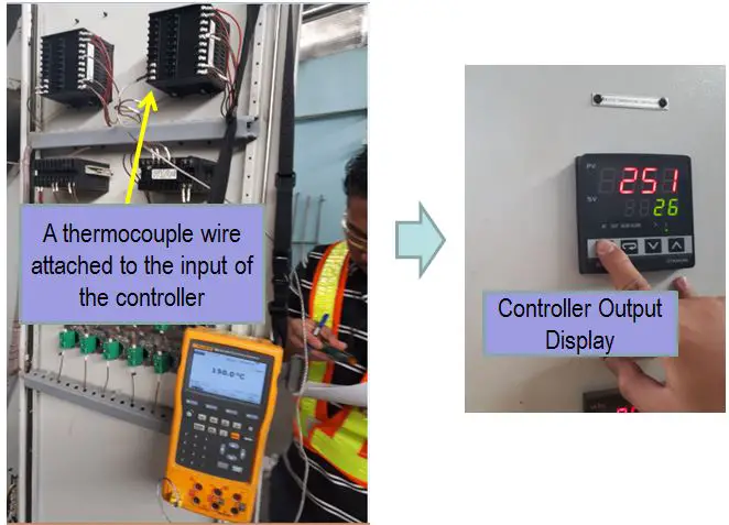
Requirements:
- Warm-up time (UUC): At least 1 hour for proper stabilization
- Temperature: 23 +/- 5 deg C
- Humidity: 50 +/- 30%
- Perform 3 trials for each range or test points
- Measurement Data Sheet (MDS)
Reference Standard and Equipment:
- Fluke 754 Documenting Process Calibrator
- Thermohygrometer – to monitor temperature and humidity
- Cleaning materials
- Thermocouple wires
Calibration Procedure for Electrical Simulation:
- Most temperature controllers are attached to a machine, observe proper safety during power on.
- Check the temperature controller for any visual defects that can affect its accuracy. Discontinue calibration if any defect is noted.
- Check the setting and configure the UUC to the thermocouple type required to be used.
- Prepare the measurement data sheet (MDS) and record all necessary details or information ( Brand, Model, serial #, etc).
- Determine the range of the temperature controller ( or the user range), choose at least 5 test point.
- Connect the calibrator to the Thermocouple terminals at the rear panel of the UUC using the appropriate thermocouple. Just follow or locate where the thermocouple used is being connected and replaced it with the thermocouple used for calibration. See figure below for a sample connection. Locations of the connections vary depending on the manufacturer. Refer to its user manual if you are not sure.
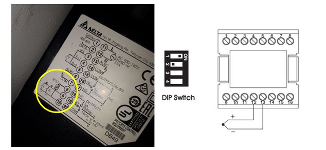
Sample rear panel thermocouple connection. Note for the symbol of the thermocouple wire, a two-piece wire connected together with a given polarity. 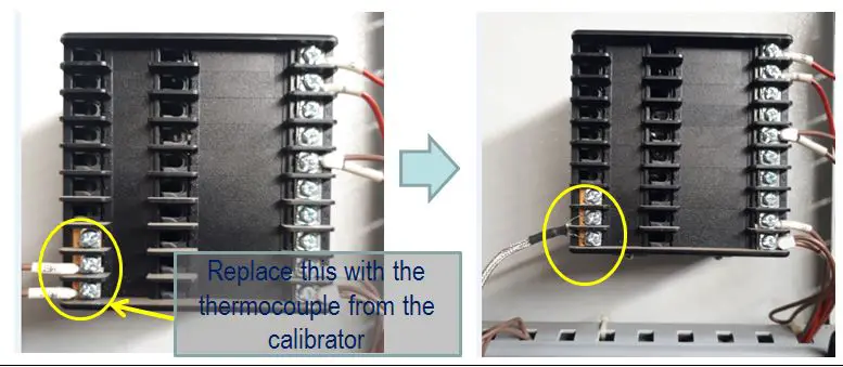
Temperature Controller Back Panel Connection - Set the Calibrator to each of the required set point values shown in Table below (or any other requirement settings). Be sure to use the source function of the calibrator.
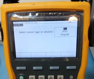
source function of Fluke 754 for thermocouple temperature simulation. - Take note of the measured values shown on the display of the Temperature Controller.
- After values are taken, secure all connections and set the UUC back to its original settings.
- Wait for the display to stabilize ( approximately 1 min) then get the reading. Record readings on the MDS.
- Continue steps 6 to 8 until all ranges are finished.
- Check readings if within the accuracy defined by the manufacturer, for example, accuracy = +/- 0.4 Deg C of reading. See below sample table for type K thermocouple used on an Omega PID Temperature Controller.
- If the readings are already within limits update the corresponding record, do labeling and sealing and issue to the owner, otherwise, do necessary repair or adjustment.

sample temp controller limits
To learn more about thermocouple calibration setup, visit this link ..3 setups for thermocouple wire calibration
2. Simulation of Actual Temperature using a Fluke Metrology Well
This procedure is accomplished through the use of a metrology well as the source of temperature. A metrology well can generate the actual temperature depending on your requirements. It has the advantage of providing the actual temperature where your thermocouple or RTD are being exposed to.
But the challenge here is that it requires a longer time of calibration because you need to stabilize the temperature settings before you can measure it. This is much applicable if you only need to verify a small range of value (an example is the min, maximum and the user range only)
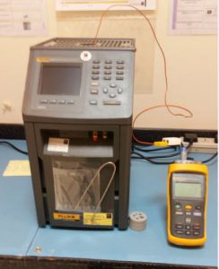
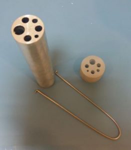
Connections of thermocouples or RTD and controllers are the same as with the first method above. The only difference is that instead of an electrical signal is simulated on the thermocouples, it will now be inserted on the metrology well to sense the actual temperature.
Select the best size of the hole in the metrology well, the more exact fit, the better. This will minimize the heat loss.
Requirements:
- Warm-up time (UUC): At least 1 hour for proper stabilization
- Temperature: 23 +/- 5 deg C
- Humidity: 50 +/- 30%
- Perform 3 trials for each range or test points
- Measurement Data Sheet (MDS)
Calibration Procedure with Metrology Well:
- Observe proper care and safety, Metrology Well generate a high temperature which can cause burn and damage.
- Check the temperature controller and its probe for any visual defects that can affect its accuracy. Discontinue calibration if any defect is noted.
- Prepare the measurement data sheet (MDS) and record all necessary details or information ( Brand, Model, serial #, etc).
- Determine the range of the temperature controller ( an example is from -30 to 700 deg Celsius), choose at least 5 test point.
- Turn on the Well and set to the desired temperature, starting from low to high temperature.
- Carefully insert the probe on the holes of the metrology well until it touches the metal block in the bottom. There are different sizes of holes so choose the one that fits properly to ensure maximum heat absorption and accuracy.
- Wait for the display to stabilize ( approximately 15 min) then get the reading, perform at least 3 trials with 2 min interval. Record readings on the MDS.
- Continue steps 4 to 7 until all ranges are finished.
- Check readings if within the accuracy defined by the manufacturer, for example, accuracy = +/-2 of reading. See the above table.
- If the readings are already within limits update the corresponding record, do labeling and sealing and issue to the owner, otherwise, do necessary repair or adjustment.
- End of Verification
3. Direct Temperature Comparison by Using a Separate Sensor and Indicator
When electrical or actual temperature simulation is not possible, this setup can be used.
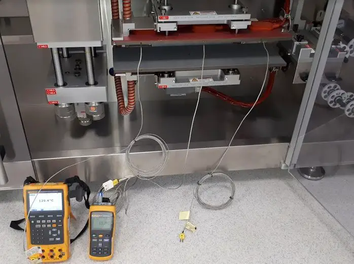
In this setup, a separate thermocouple is tapped or inserted into the heating element in order to directly sense the temperature, the temperature readout is compared with the reference indicator.
A good reading is ensured by a properly inserted or clamped thermocouple into the metal plate or heating element.
You may use the calibration procedure for the metrology well in this setup (No. 2). The only difference is that we are using a separate indicator as our reference standard but the principle is the same. We will also compare the temperature readout of the temperature controller with the reference indicator.
Please see the image below to understand more.
Temperature Controller Troubleshooting
The methods I have presented above is also useful in troubleshooting a temperature controller. You can isolate both the controller and the sensor to determine functionality.
The best method to use for troubleshooting is method 1, with the help of a process calibrator like Fluke 754, you can easily perform test and verification because of the simulation capability of the process calibrator.
Most common temperature controller error that I encountered are:
- Out of tolerance reading
- Intermittent alarm or no Alarm.
- Out of range due to broken or open connection of temperature sensor.
The above problems can be easily detected and corrected using the process calibrator. Every brand or model of temperature controllers have different settings, so make sure to have the temperature controller manual to determine the codes or passwords in order to easily access the adjustment or configuration settings.
Conclusion
I have discussed here the 5 ways to calibrate a temperature controller. But the main procedure and setup only fall in these three, namely electrical simulation, actual temperature simulation, and direct temperature comparison.
A good assessment must be applied on how to choose the method in order to sense and display the signal. In any case that you encounter a different setup, you have an option to apply what is best to use.
Thank you for visiting my site, please comment and subscribe
Edwin.

19 Responses
neenu Thomas
where is the 3,4 and 5th method?
edsponce
Hi Neenu,
Thank you for reading my post. The 3rd, 4th and 5th method are stated in the mid part of the post.
Please see below:
3rd method: The third one is by measuring the temperature directly inside an enclosed system using a separate sensor and indicator then comparing its display with the temperature controller. This is usually applied to most ovens or furnace. Check this link https://calibrationawareness.com/electric-oven-calibration-setup-and-procedure
4th method: The Fourth is a simulated voltage (in mV), resistance (for RTD) and current like the 4-20 mA depending on the settings or programming of the temperature controller. ( mostly related to method 1)
5th Method: This is by comparing the display of the temperature controller to a more accurate temperature indicator with a separate sensor. But in this method, the sensors are clamped, inserted or fastened by screws. This can be seen in hot surfaces or hot plates.
Thank you for your comment. I will consider to include more photos and expand more the 3rd to the 5th method.
Thanks and regards,
Edwin
Thomas Bates
Hello,
In the simulation method (1), did you use compensating cable or an extension cable. I have been told the difference between these two wires although looking the exact same can change results due to the compounds inside the wire.
edsponce
Hi Mr. Thomas,
I did not use a compensating cable or extension cable. I used directly the thermocouple wires.
Thanks for visiting my site.
Best Regards,
Edwin
Luis
Thank you!!, i have a question, the tolerance for the accuracy depend of brand of temperature Controller? or exist a Standard reference Table?
regards
edsponce
Hi Luis,
You are welcome.
Yes, tolerance depends on the accuracy rating as per manufacturer specifications, but mostly depends on the user tolerance.
I have seen some processes where tolerance are based on the combinations of many contributors, tolerances are the results of the combination of below factors:
a. accuracy of the controller
b. accuracy of the reference standard
c. uncertainty result of the standard
d. other significant contributors
Thank you for reading my post.
Edwin
Stacy
Hi, how do we set the tolerance if I do not have any information on manufacturer specification?
edsponce
Hi Stacy,
There are a number of ways where you can reference your tolerance, below are some of my recommendations as per my experience:
1. your process tolerance
2. The uncertainty results from its calibration certificate
3. perform a repeatability and reproducibility study and use the final results as tolerance.
4. you may add all the sources of errors or tolerances,
example: tolerance of the standard + tolerance of the process + resolution + instrument error = total tolerance
Just remember that you need to document in your procedure what tolerance calculation you have chosen.
I hope this helps.
Edwin
Kirk Thomas
Hi, good day. How do I actually make the adjustment on the controller if the temperature does not match the output of the calibrator.
edsponce
Hi Kirk,
Depending on the model of the controller, there is an ‘offset mode’ where you can add or subtract a value to offset the reading of the controller and match the output value of the calibrator. You need to check the user manual for this.
I hope this helps,
Edwin
Kirk Thomas
Thanks Edwin.
Kirk Thomas
Thanks. I got through.
Kirk
edsponce
Hi Kirk,
You are welcome, glad to know you got through it.
Best Regards,
Edwin
chris okechukwu
hello guys,
please i need some help. a temperature controller is not displaying corresponding increase in temperature. The temperature increase is very slow , but the controller cut off the heating element at at a lower preset value of temperature
displayed on the temperature controller
edsponce
Hi Chris,
Can you tell what sensor are you using? have you tried using other thermometer to compare the readings displayed on the controller?
Edwin
Shobuj
Thanks for your information.
edsponce
You are welcome
Donnie
How do you adjust the temp setting on a STC 600 controller. Its off by 15 deg
edsponce
Hi Donnie,
MOst Temperature controllers Temp setting can be easily adjusted by using the up and down button once you have reached the User-Temp setting mode by pressing the “set” button. There is also an “Offset” setting when you want to adjust it after verification. You need the user manual for further understanding because there are codes that you need to know in order to access it.
Best regards,
Edwin