During my learning days, when I hear a pressure transmitter (and other transmitters), it seems it is a very complicated instrument to calibrate (How about you?).
.
But when I already learned and experience calibrating it, I can say that it is just calibrating a simple pressure gauge. the only difference is that the applied pressure is now converted into a current output, the 4 to 20 mA signal. In order to be understood by the user, it will be converted back to pressure units by the PLC display.
.
We do not need to know how to operate a PLC (but it is better if we do), what we need is, during calibration, it is important that the operator of the PLC is with you, make the user operate while you perform the calibration.
.
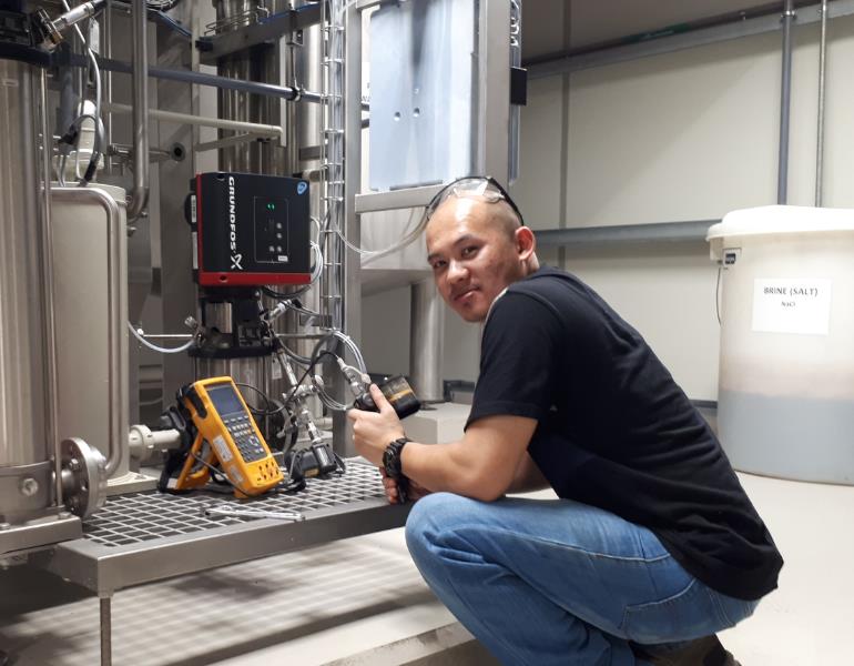
This simple pressure transducer is a transmitter because it is used from a remote location going to a control panel (PLC) to monitor and control the process involving pressure. The signal is transmitted through a wire in the form of a standardize signal which is the current, the 4 to 20 mA signal.
.
In transmitter calibration, not just pressure transmitter, an additional knowledge about linear interpolation is needed to understand the conversion of current output to pressure units or other units or vice versa. I get to be confused about this conversion when I was newly exposed to this so I will include the conversion formula here (just in case you are confused too). Just read on.
.
In this post, I will present the following:
-
3 ways to set up a pressure transmitter for calibration.
-
Loop calibration set-up
- Individual or Isolated Instrument Setup
- Current Meter In-Series Connection Setup
-
- 3 types of pressure transmitter connector
- what standard to use in calibrating a pressure transmitter and how it is connected and configured
-
The conversion of pressure to current using manual computation ( or by using a method called linear interpolation)
-
Calibration procedure
.
Instrument Classification
Sometimes, we are getting confused whether an instrument is a transmitter or a transducer. For us to see the difference, below are the instrument classification directly taken from IEC 60770-1:2010.
(–) stands for any physical, electrical or chemical quantity to be measured and processed, such as pressure, temperature, level, flow rate, density, pH, composition, as reported below:
a) (–) transmitter a measuring transducer whose output is a standardized signal
b) (–) meter an instrument intended to measure a physical quantity
c) (–) indicator an instrument intended to visually indicate a physical quantity
d) (–) switch a measuring transducer whose output is a binary signal (ON/OFF or 0/I)
e) (–) transducer a device which accepts information in the form of a physical quantity and converts it into information in the form of the same or another physical quantity according to a definite law
f) (–) sensor an electric signal transducer that converts a signal of any kind into an electric signal
Pressure Transmitter Calibration Set-Up
There are 3 ways that we can set-up a pressure transmitter calibration.
-
Loop Calibration Setup
What is loop calibration?
Loop calibration is a calibration setup where the instrument is calibrated as a whole involving the pressure sensor and transmitter inter-connected to the PLC display. It is a calibration method where the instrument is calibrated in its actual location where it is installed and in operation, but it is isolated in order not to affect other processes.
.
The advantage of this is that you are getting the overall performance of the instrument. you can determine the overall functionality of the loop.
.
The disadvantage is that if there is an error, you can not tell immediately what is causing it and troubleshooting may take longer.
.
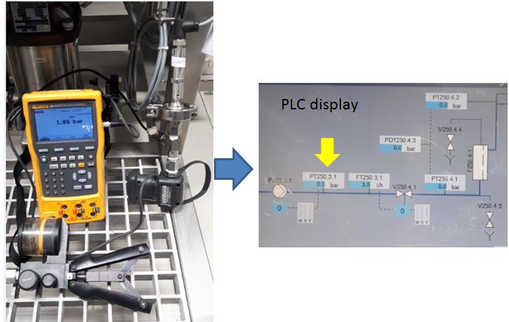
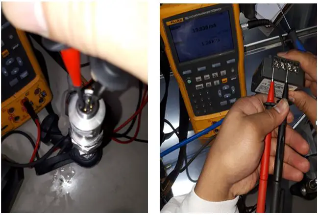
Loop calibration involves a 4 to 20 mA signal. Readings can be taken as current units or pressure units. Current is the signal that is being sent to the PLC Display but it is converted back to pressure units.
.
If you want to get the current readings, you need to connect a multimeter that is in series with the wire going to the PLC.
See no. 3 set up below.
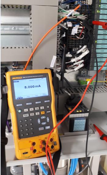
Below is the set up for loop calibration:
-
Remove the installation of the pressure transmitter on its location (to expose the pressure input). Do not remove cable or wiring connections.
-
Using the proper fittings and connectors, connect the calibrator pressure output to the input of the instrument.
-
See to it that there is no leak.
-
Check and ensure correct tagging or ID in the PLC display to match with the transmitter in order to see the readings once the pressure is applied.
- If you want to check the current value while applying pressure, you may do simultaneously the setup no 3. below.
-
It is now ready for calibration.
-
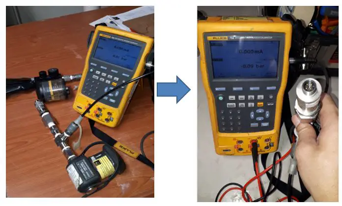
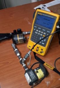
Individual or Isolated Instrument Setup
In this setup (which is also called Bench Calibration since it is removed from its installation), we will isolate the main instrument to other connections, only the main sensor that is directly tapped to our reference standard and reading is taken directly on the display of our transmitter calibrator.
.
This method is more accurate because no other outside sources of error are present. Troubleshooting is easy, you can directly determine the problem because you are just concentrating on the instrument itself.
.
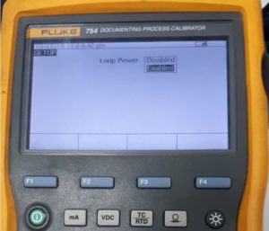
But the disadvantage is that mistakes may occur during the re-installation. So be careful not to interchange connections. Also, you need a special calibrator with a loop power to perform this. This is one of the special capabilities of Fluke 754 as a transmitter calibrator.
.
Instrument-only calibration involves the output signal which is directly displayed as 4 to 20 mA. You need to apply interpolation in order to determine or convert it to pressure value or units.
.
How to use interpolation or to convert pressure to current? Continue reading further…
.
Individual Instrument Calibration Setup
-
Remove the instrument from its location including its connecting wires. Ensure there are no other power lines to be disturbed.
-
Connect the calibrator supply pressure to its input or instrument sensor. This is the same as the loop connection setup. But this time, the instrument is isolated.
-
Since the connecting wires are removed, the output ports are exposed. Check the transmitter connection diagram or label to ensure proper functioning and output signal detection.
-
Since the transmitter is disconnected to its line, there is no power to it, in this case, we will enable the loop power of Fluke 754 pressure transmitter calibrator to supply it in the transmitter.
Pressure Transmitter output connection- Enable loop power of Fluke 754 for this procedure. -
At the same time and connection, we can read the output current that is based on the supplied pressure.
-
Through linear interpolation, we can determine the output in pressure units.
-
Compare computed value on the displayed value if within the expected tolerances.
-
Current Meter In-Series Connection Setup
This setup is the easiest and most simple to perform. Just connect the Fluke 754 probe (or simply a calibrated multimeter) in series with the circuit or the transmitter current path and directly measure the actual current.
.
This procedure may not be a stand-alone or sufficient procedure, it is preferred to perform together with setup no 1, but if there is no other option and the user approves this procedure, then it may not be a problem.
.
This set up does not need any access or connection from the transmitter itself, only verifying the actual current then compute for the converted pressure value. The only thing you can measure is 0 pressure (4mA) and the actual pressure that is used in the process.
.
Some instruments have easy access where you can directly tap the current meter to a dedicated current-output port to get the current reading.
The main standard used in Pressure Transmitter Calibration- Pressure Transmitter Calibrator
I believe we are now familiar with FLuke 754 as a reference standard for pressure calibration
especially transmitters. There are other process calibrators out there but this is what I always use since I started pressure calibration. It has pressure modules that have different ranges depending on your needs.
If you have a lot of instruments involving pressure and temperature instruments, this calibrator is a must.
See the related article in this post about 11 Ways to use Fluke 754..
3 Types of Pressure Transmitter Fittings/Connector
The pressure transmitter has different connections and design depending on its use or purpose. Below are some types of pressure transmitter connectors that I encounter:
- Diaphragm type connections– mostly used in a pharmaceutical company. Used in a liquid that has a solid particle that can clog on a simple NPT connector. I always like calibrating this type of connector because you can easily remove and return the unit. But sometimes, you need a dedicated fitting in order to connect it to the calibrator. For us, we need to have it manually fabricated in order to use it.
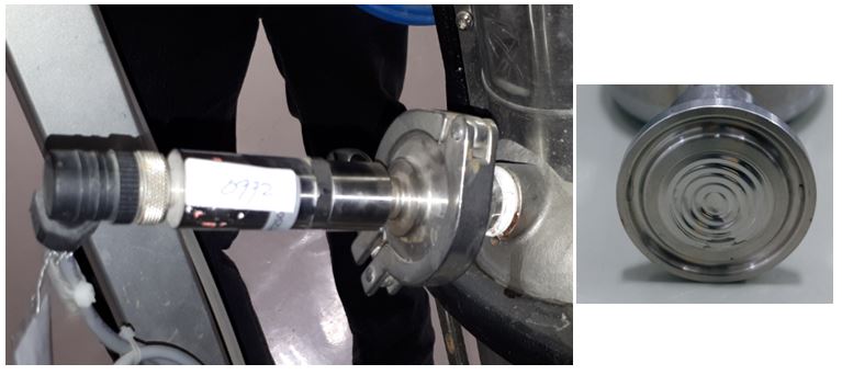
Diaphragm Sensor and Fittings
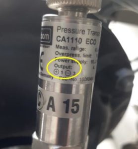
- NPT type connector– the most common type of connectors being used for general purpose. This is a 1/2 size NPT which is what we usually encounter.
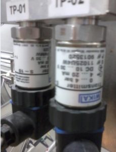
Pressure Transmitter with 1/2 NPT Fittings
- Vinyl Tube or Rubber Fittings for differential pressure– used for low-level pressures and mostly air is the medium used. As for its calibration, it is the same as a regular differential pressure gauge, just supply pressure to its positive side and let the negative side exposed to ambient. For more info about differential pressure calibration, visit my post here –Differential Pressure Gauge.
Using the loop power for transmitters with no power supplied to it.
By enabling this in fluke 754 ( or other process calibrators with the same capability), you can power up a transmitter and read the 4 to 20 mA output signal. No other connections or power supply needed.
Pressure Transmitter Calibration Procedure
-
Inspect the UUC ( Unit Under Calibration) visually for any signs of damage (leakage or broken wires) and cleanliness issues. Record observations on your datasheet
-
Connect the pressure transmitter on the pressure hose of the pressure module (use appropriate fittings). See to it that there is no leakage. Refer to the 3 ways setups above
-
Allow proper stabilization of the UUC and the reference standard (at least 30 minutes).
-
Prepare your measurement data sheet where the current to pressure conversion are listed. (See below on how to convert using interpolation)–What is a Measurement Data Sheet (MDS)? visit this link to learn more>>MDS
-
Record five test points that are uniformly distributed on the range of the pressure transmitter, preferably 0%, 25%, 50% 75% and 100% of the range.
-
Prepare the hydraulic pump ( or pneumatic pump if necessary). Close the Bleeder knob of the hand pump
-
Do not apply pressure yet to the hand pump, this is the Zero pressure setting. The current value should be equal to 4 mA. Check the display on the Fluke 754.
-
Take note of the measured value and record on your datasheet.
-
Apply the next pressure range and record the equivalent current value.
-
Continue until all ranges are completed.
-
Repeat the procedures for the 2nd trial each range.
-
Make sure that all readings are within tolerances provided.
-
If adjustment is needed, make sure to read the instruction or service manual. methods of adjustments are different for every manufacturer.
Using Manual Computation or Linear Interpolation as a Method for Converting Different Output Units to Current.
There is a formula that we can easily use to convert most (or all) units utilizing 4 to 20 mA signal to mA units. There are others out there but this is the simplest I know.
Below is a simple formula for pressure to current conversion.
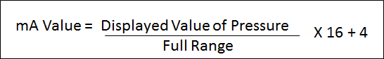
For example:
range is : 0 to 10 Bar
Full range = 10 Bar
Displayed or measured value: 7 Bar
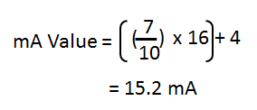
15.2 mA is the equivalent current value of a 7 Bar pressure.
For Value or range which is not starting with zero ( with a vacuum range), use below linear interpolation formula.
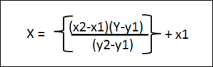
You can also encode this to excel for easier conversion.
If you want to know and calculate the error, Just subtract the True value with your computed value.
Error = Measured Value – True Value
.
If the Pressure Transmitter has an accuracy of 0.5% of the range, then 0.005 x 7= +/-0.035 Bar, you can use this as the tolerance to determine a pass or fail results. Or you can ask the user for their respective tolerances.
To learn more about the differences of Error, Uncertainty, and Tolerance, visit my other post here>> differences between accuracy, error, tolerance, and uncertainty
Conclusion
Transmitters are very useful instruments in monitoring and controlling a process remotely. One of this is the pressure transmitter, like other transmitters, a pressure transmitter is also using a 4 to 20 mA signal which can be measured and converted into the desired unit. In this post, I have discussed and shown the 3 setups that I always performed during pressure transmitter calibration. I also presented the different connections and fittings that you may encounter during calibration. and lastly, I presented how to calculate and convert a pressure value to current value using a simple conversion formula.
.
Do you experience other setup and standards for calibrating a pressure transmitter? Comment below.
If you like my post please share and subscribe.
.
Your calibration friend,
Edwin
37 Responses
Joseph Rentoy
Thanks for the information please post more calibration procedure of other instruments godbless
edsponce
Hi Joseph,
Thank you for reading my post. Do you have something in mind
what instruments that I can include in my future post?
Thanks and regards,
Edwin
Mario fonseca
Many thanks, @Edwin for this precious information you’ve been sharing.kgw
edsponce
Hi Mario,
It’s my pleasure. I am glad you liked it.
Best regards,
Edwin
Orville Darr
How do you go about calibrating a vacum gauge using the Fluke 574?
edsponce
Hi Orville,
Thank you for the comment.
Fluke 754 has a different pressure module which you can choose with a dedicated pneumatic pump. The pneumatic pump (Fluke 700PTP-1) can be set to pump a negative pressure (vacuum) and the pressure module is the sensor to measure the vacuum input displayed in Fluke 754.
Regards,
Edwin
Ravensky Stewart
—— This simple pressure transducer is a transmitter because it is used from a remote location going to a control panel (PLC) to monitor and control the process involving pressure. The signal is transmitted through a wire in the form of a current (the 4 to 20 mA signal)..——
Transducer and transmitter are different thing
edsponce
Hi Mr. Ravensky,
Thank you for taking time reading my post.
Yes, you are right, transducer and transmitter are different things. The transducer is the sensor that converts the analog (pressure) input signal to current while the transmitter is the one who transmits the signal through the cables attached. They are packaged as one in a pressure transmitter.
Thank you for the comment, appreciate your inputs if you can add more.
Thanks and regards,
Edwin
JOHN MULINDI
Well described procedure, I think any instrument technician can follow this procedure without a problem.
edsponce
Hi Mr. John,
Thank you for your comment once again. I Appreciate you liked it.
Best regards,
Edwin
Ejenavi O.
Edwin, your pattern of giving out knowledge is highly commendable. The lessons are very good for hands on. Thanks and keep the good work.
edsponce
Hi Ejenavi,
You are welcome. Appreciate the comment.
Best regards,
Edwin
Rham Sobrevilla
Hi Edwin,
I enjoy reading with your calibration awareness post. I have concern regarding calculation of errors. Of certain pressure transmitter 5 points calibration test. Hence the Accuracy of PT UUT is 0.5%FS can you share how will calculate the errors OR FORMULA TO BE USED in determining whether the hystheresis pass or fail against the required accuracy of the uut. Let say i will disregard the plant required accuracy. I am refering only the UUT required accuracy. What formula I am using currently is Error = actual value – ideal value/ Span ×100 for every increment test point. Example: actual value is 4.09mA – 4mA/16mA ×100. Then the result of this is to compare with required accuracy of the UUT. To determine whether pass or fail.
Please comment or correct me if i am using the wrong way. Thank you and appreciate for your reply.
Rham.
edsponce
Hi Rham,
Thank you for reading my post, I appreciate it.
Your method of error computation is correct; you are just converting the error in the percentage of the span.
But based on your example, you need first to calculate the actual value of the transmitter accuracy which is 0.5% of FS(Full scale). For me, it is better to use values in mA units first, then convert it to a percentage later.
This is what I do in calibration; I will compare the accuracy of the pressure transmitter based on the output of the reference standards.
During this comparison, I can determine the error in this formula:
> Error = Actual value-Ideal value
For example:
The reference standard reading is 4.000 mA and the pressure transmitter is 4.09 mA
> Error= 4.09-4.000 = 0.09 mA >> actual error of the pressure transmitter
If the accuracy of your pressure transmitter is 0.5%of FS, where FS = 20 mA,
> Transmitter accuracy=20*(0.5/100) = +/- 0.1 mA;
Now, we will compare it with the computed error.
> Since 0.09 mA is less than 0.1 mA, therefore, it is PASSED
Please note that the formula for calculating the pressure transmitter accuracy is different for every manufacturer. You need to consult its user manual.
Hope this helps
Edwin
SREEJITH R
HI EDWIN ..
please tell how to calibrate pressure tranmitters using HART375 , 475
AMS TREX Device Communicator
please tell how to calibrate pressure transmitters using AMS TREX Device Communicator
James Peterson
You are spot on with all of your information. I personally think too many people dwell too much into formulas this day and age most of everything is computed for us.. I think your write up was great. I questioned the transducer/transmitter at first but it depends how you look at it so i will give you that one. I can tell by your verbage and examples you are a seasoned Tech. Thank you for the read.
edsponce
Hi Mr. James,
You are welcome and thank you for the positive comments, I appreciate it.
Yes, I agree with you, nowadays almost everything is automated where manual calculations are almost forgotten. This is the basic so it is an advantage if we can implement it.
Thank you for your understanding and advise regarding the transducer/ transmitter thing.
I can also tell that you are a more seasoned tech the way you understand my article. I appreciate much your comments and hoping to see more of it.
Best Regards,
Edwin
Tobi
Hello Edwin,
I so much gathered enough information from your write up above. I am just new in the system of pressure calibration, still learning, and yet to carry out a real project on it. I am learning on how to use Fluke 726, trying to gather as much information as as far as pressure calibration is concerned. Please i need you to clarify the following questions concisely for me:
1. In pressure calibration, must the calibrator always display the source pressure and the equivalent measured output current? I asked this in regard to the first method in the set up (using the loop calibration set up). I could see that only the pressure module terminal was connected from the calibrator to the pressure module. The mA ports weren’t connected because the transmitter was still connected to the power supply from the process line.
2. I read so far that when you calibrate in the first place, if the tolerance of the result is more than the set tolerance, then there is a need for adjustment, and then recalibration. Can we have a situation in which after recalibration (that the second time), the tolerance is still more than the set tolerance? What can be the likely causes of this?
3. Are all the tolerances of the result (i.e. each of the test points, 0%, 50%, 100% for instance used for comparison with the set tolerance?
4. Which tolerance is being used for comparison with the set tolerance? source pressure tolerance or measured current tolerance? or whose tolerance is being set to determine pass or fail? source pressure or measured current?
Looking forward to your earliest response to these questions.
Thank you
edsponce
Hi Tobi,
Thank you for visiting my site.
Below are the answers as per my understanding of your questions.
Question 1. In pressure calibration, must the calibrator always display the source pressure and the equivalent measured output current? I asked this in regard to the first method in the set up (using the loop calibration set up). I could see that only the pressure module terminal was connected from the calibrator to the pressure module. The mA ports weren’t connected because the transmitter was still connected to the power supply from the process line.
Answers:
Yes, you are correct. I made this article where I separated each measurement procedure. The loop calibration involves the PLC display and the pressure transmitter that is why I separate the current measure and the actual pressure. In this procedure, I use the PLC as the display so it is a direct pressure to pressure readout. But if you can connect the fluke 726 probe in series with the line (same as multimeter function, you can also read the equivalent current). See no 3 set up.
But if you want to calibrate the transmitter only, you can use the No.2 procedure above. You will supply the needed pressure (source) and read the equivalent output in current value. This can be displayed as current with the equivalent pressure value in the calibrator. (make sure that loop power is enabled in your calibrator if the transmitter is passive, meaning, the power supply is separate).
Question 2. I read so far that when you calibrate in the first place, if the tolerance of the result is more than the set tolerance, then there is a need for adjustment, and then recalibration. Can we have a situation in which after recalibration (that the second time), the tolerance is still more than the set tolerance? What can be the likely causes of this?
Answers:
I believe you are referring to the UUT output reading versus tolerance. Yes, that happens, that is why we need to have a good schedule of recalibration if we know that a UUT is drifting every time we perform calibration.
There are so many reasons and below are some that I observe and encountered:
1. due to old age, where drift normally happens on its electronics components
2. due to environmental conditions.
a. Exposure to extreme temperatures
b. Strong vibrations
c. Contaminants like dust and rust or chemical reactions which affect the contacts
3. Overpressure
4. Aging sensors
5. Sometimes, calibrators itself is the problem. You need to perform an intermediate check to ensure accuracy.
Question 3. Are all the tolerances of the result (i.e. each of the test points, 0%, 50%, 100% for instance used for comparison with the set tolerance?
Answers:
Yes and No
During calibration, we will perform and check the accuracy to cover the full range as per the procedure.
Normally during verification, every test points are verified if it is still within the tolerance specified by the user or as per manufacturer specifications.
But in some instances, the decision on what to check and accept if within tolerance depends on the range of use. For example, the results of verification from 10% to 30% is Failed but on 40% to 100% it is Passed. But based on your process, you are only using the 60% to 80% range. Therefore, you can still use the instruments since it is acceptable on the user range.
Question 4. Which tolerance is being used for comparison with the set tolerance? source pressure tolerance or measured current tolerance? or whose tolerance is being set to determine pass or fail? source pressure or measured current?
Answers:
You will use both, the current value and the pressure value.
Since there is a direct conversion of current to pressure as per the formula I shared above, I suggest measuring first the current value then converting it to pressure than making the verification.
Also, most manufacturers are using a pressure parameter as the basis of tolerance, for example, 0.5% of Full-scale or span of pressure output. It is only a matter of conversion.
The first thing you should do is to organize your data in a table. See the table below. As you can see on the table below, current and pressure are interchangeable, the important thing to remember is you know the expected value before you make a measurement and verification.
For example:
The Pressure transmitter has a tolerance of 0.5% of Full Scale. The full-scale range is 20 Bar
range is : 0 to 20 Bar
Full range = 20 Bar
Tolerance : 0.005 x 20 = 0.1 Bar
I hope this answers your questions.
Thanks and regards,
Edwin
Tobi
Good day Edwin,
The Fluke 726 and its accessories have arrived at our office here in Nigeria. However we are having challenges in calibrating a differential pressure transmitter, We followed the steps given in the Fluke 726 instruction manual. Something is not that clear to my team-If you can help out with this statement (last step): how to perform check at 10% and 100% of span using Fluke 726 based on your knowledge of any similar calibrator, we will really appreciate you.
The differential pressure has been calibrated within the measuring range: 0 in H20 4 oC to 600 in H20 4 oC, but we want to calibrate it to function between 0 in H20 4 oC to 400 in H20 4 oC.
Your contribution will be highly welcome.
Thank you!
edsponce
Hi Tobi,
Good to know that you already have the calibrator.
Regarding your concern, it seems that you need to perform first an adjustment or reconfiguration of the transmitter before executing the calibration and verification part.
Depending on the model of the transmitter, you need to check on how to reconfigure the range. You need to align it to the range that you require. Check if you can adjust it manually.
Most transmitters that are powered by HART technology can be reconfigured using the communicator provided by the manufacturer. You can also use the HART function of Fluke 754. Fluke 726 I believe can only read HART output but cannot make adjustment. Check this out to be sure.
I found a good video of transmitter adjustment using Fluke 754 HART function for additional reference in this link.
After you performed the adjustment or reconfiguration, you can now perform the calibration procedure that I have presented in my post.
Hope this helps,
Edwin
Saahoo
Can i know what is the Maximun % error for calibration of a pressure transmitter
edsponce
Hi Saahoo,
Maximum % error are based on the accuracy specifications of the manufacturer. You need to check it on its manual.
Errors are best understand when translated as tolerance, where you can use the process or user tolerance as the maximum or acceptable error to be used as an acceptance criteria.
Hope this helps,
Edwin
Eric Marcelo
Hi Edwin,
This has been a bone of contention between me and several calibration technicians.
In most reports I’ve seen, say for a pressure transmitter, the technician will write the set pressure (as the input) and the current (mA) as the output. Then they have another column that gives the equivalent current of the pressure for calculating the error.
My method is to convert the current output to its equivalent pressure and calculate the error using the set pressure and the equivalent pressure. Therefore, the error column will have the difference in pressure units instead of milliamps.
My reason is because if I have to make a report to a production supervisor or manager, they will not be able to tell how well, or how badly, the instrument is functioning if I give them the figure in milliamps. It has no meaning for them. Giving them the figure in pressure units (in this case) makes more sense to them.
edsponce
Hi Sir Eric,
I appreciated the extra effort that you put in reporting of your results. It is indeed very helpful in interpreting the results.
About the scenario that you have shared above, both are correct.
I just want to share some important thoughts about reporting of results. Before we report the final results in a calibration certificate, there are requirements that we need to consider. These are:
1. The requirements of the customers.
2. The requirements of the method or calibration procedure
3. The requirements of the standards.
If you observed, I have placed the requirements of the customer as no.1. This is because, before we perform the calibration procedure, we need first to determine the requirements of the customers if any. If none, then we can now proceed to perform the calibration and reporting as per our standard procedure.
Then as per the requirements of the standards, ISO 17025:2017-Reporting of results, under clause 7.8.1.3 , it states that: “When agreed with the customer, the results may be reported in a simplified way”.
As we can see, as long that a costumer is informed and agreed to what we need to do to make it simple for them (or to us) to understand the results, then it is ok.
It is also part of our service and to show our expertise by interpreting the results for them.
The important thing is to record or document any actions that we do where there are important changes that takes place that is specific to a certain customers, specifically customer requirements, request, or approval.
I hope I answered your concern.
Edwin
akbarabadi
Hi
I have a question about calibration of pen pressure transmitter in water?
How does the factory calibrate it?
edsponce
Hi Akbarabadi,
I am not familiar about a pen pressure transmitter, but if it is a transmitter then you can remove it and supply a pressure on its inlet port.
Thanks and regards,
Edwin
akbarabadi
hi
tks
Can you tell me the steps of calibrating the pressure transmitter?
Is it 24 hours to zero after calibration?
Need to perform a step pressure for each pressure transmitter in the calibration?
edsponce
Hi,
what do you mean 24 hrs to zero? please provide more details.
Best regards,
Edwin
edsponce
Hi,
I already presented a simple transmitter calibration procedure above. I am not familiar with the “24 hours to zero” process of calibration. Is there a specific standard procedure you follow? or maybe a manufacturer recommendation?
I am only familiar with the increasing and decreasing steps of calibration. Increase pressure until maximum range then decreases it afterward with the same test points.
Please add more details to your concern.
Thanks for reading my post.
Edwin
JR
Enjoy reading your blog. Could you please talk about PID controllers and its operational theory in an easier ways. Thanks
edsponce
Hi JR,
Thanks for reading. I will add your concern to my list for future posts.
Thanks for the comments.
Best regards,
Edwin
akbarabadi
Hi
Can you tell me the steps of calibrating the pressure transmitter?
Is it 24 hours to zero after calibration?
Need to perform a step pressure for each pressure transmitter in the calibration?
akbarabadi
its for pressure without hart protocol , with pga309 in factory
Annie
Hi,
can you please let me know where to get the full document of SOP of intermediate check?
edsponce
Hi Annie,
I do not have a full document of SOP, but I have an article about intermediate check that you can read on as a guide in this link >> Intermediate Check guide
Check it out if it answers your concerns.
I hope it helps,
Edwin