Measuring or verifying the airflow coming out from the output end of the duct is very simple, an easy way is to use a vane anemometer. A simple placement of the vane (fan) in front of the opening of the duct directly measures the wind velocity or volume flow.
But what if the opening or the output end of the duct is not accessible? It is here where we can use the Pitot Tube Anemometer. We just need a small opening anywhere in the duct or pipe to insert the Pitot tube.
In this post, I will share with you the following:
- The basic principle of the Pitot Tube Anemometer
- How to verify the velocity and airflow in a duct using a Pitot Tube Anemometer
- Using A Pitot Tube Anemometer to calibrate the volume flow transmitter used in the duct.
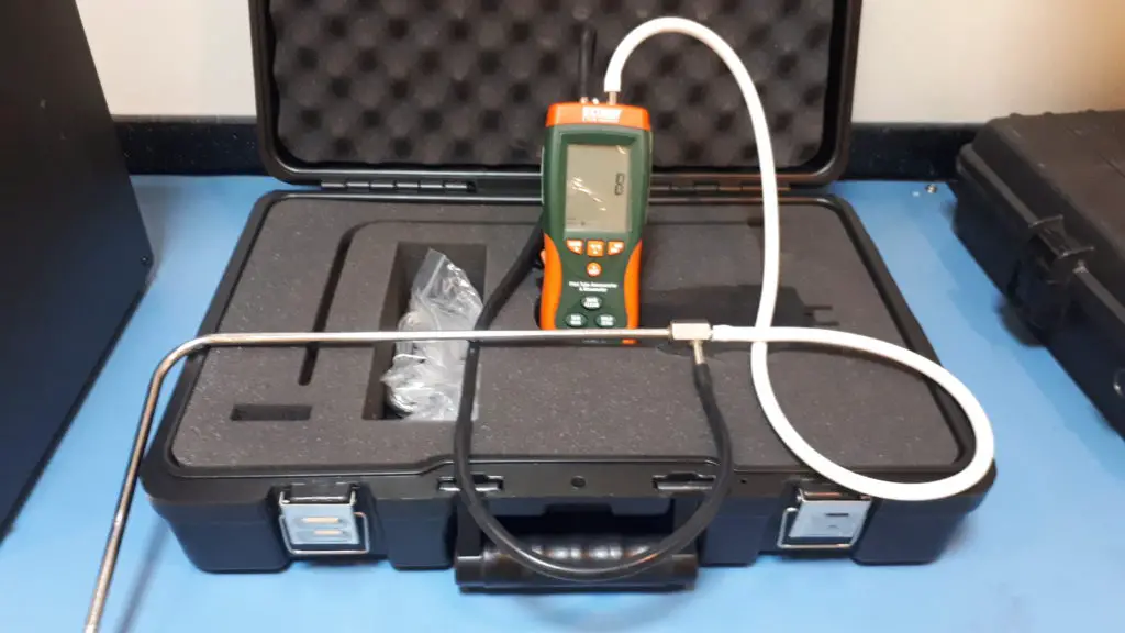
This type of instrument is still new to me, but I wanted to share with you to be familiar with a pitot tube and it will also give you some ideas on how to use it. This instrument is the Extech HD350 Pitot Tube Anemometer
The Pitot Tube – Where to use a Pitot Tube Anemometer
If you are familiar with the vane anemometer, then you can relate to this easily. It has the same application but with a different method and approach of measurement.
A pitot tube is used to measure the velocity of air in a duct with just a small opening. The basis of measurement is through the use of Bernoulli’s principle.
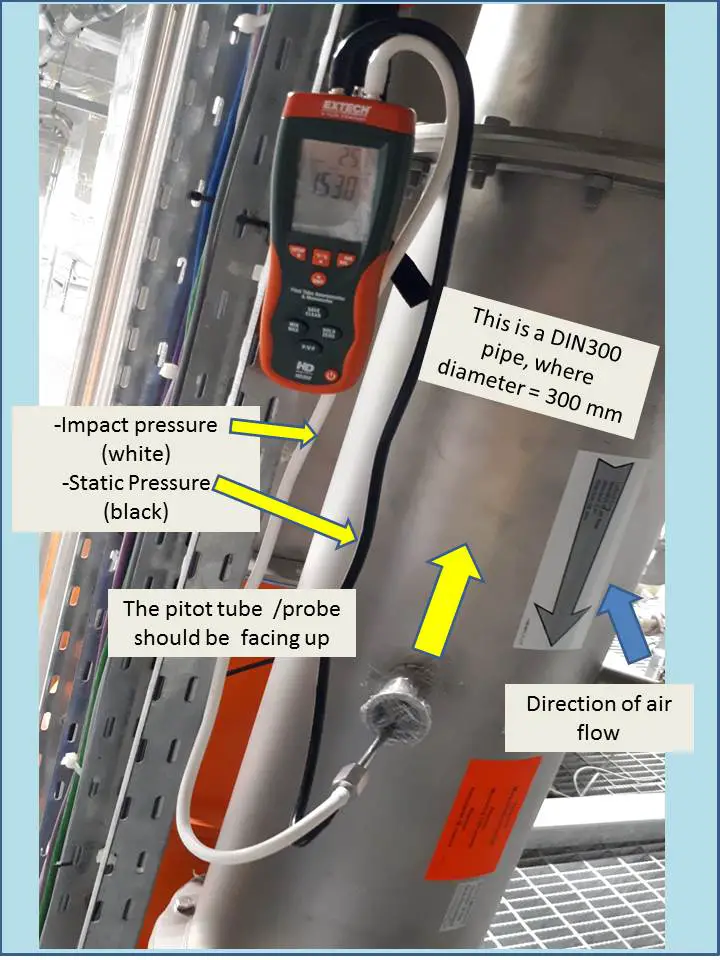
In simple terms, we can calculate the velocity of the fluid (air) inside a duct or channel by determining the differential pressure. These pressures are the Impact pressure and the Static pressure (see photo below).
To simplify the calculation, below is the simplified formula to calculate the velocity of the air in a duct which is related to differential pressure:
V = 1.29 x(√ΔP) in m/s
V = 4005 x(√ΔP) in ft/min
Where:
ΔP = The differential pressure (Pa, psi) measured by the pressure sensor which is the Velocity Pressure (Impact pressure – Static Pressure)
V = velocity

The advantage of this method is that it is easy to set up without disturbing the process. It means that there is no need to schedule a shutdown. You only need a dedicated port, or a hole to insert the tube, and basing it on the duct where we perform the verification, it is already available as per design.
During execution, one main disadvantage that I observed is that you need to properly align and position the hole of the pitot tube perpendicular to the airflow in order to get the most accurate reading.
Read on to know more….
I have watched below video that explains well on how to use and position the Pitot tube Anemometer, check it out.
I also read a good article about Pitot Tube in this link: The advantages and disadvantages of using a pitot tube
Extech HD350 Pitot Tube Anemometer Measurement Capabilities
This is a manometer air flow measuring instrument that utilizes the differential pressure output to measure airflow or volume flow.
Extech Pitot Tube Anemometer has 5 measurement capabilities, it can:
- be used as a manometer – a low pressure measuring instrument
- be used as differential pressure, it has two separate ports for low and high pressure
- measure ambient temperature- used as a thermometer
- measure the velocity of air (speed)
- measure the volume flow of air or airflow.
Air Flow Measurement Setup in a Duct Using a Pitot Tube Anemometer
Air Flow is measured first by determining the airflow velocity and then determining the dimension of the duct to calculate the volume flow.
How to Measure the Velocity of the Duct with Extech Pitot tube?
The velocity is based on a differential pressure measured by the pitot tube anemometer.
If you want to calculate manually, below is the formula: (same above)
V = 1.29 x(√ΔP) in m/s
V = 4005 x(√ΔP) in ft/min
Where: ΔP = The differential pressure measured by the pressure sensor which is the Velocity Pressure ( Impact pressure – Static Pressure)
The good thing is when using the Extech HD350, it will directly be displayed as velocity, a calculation is not needed
You only need to go to the settings and set to velocity and you are done, no other settings are needed.
Just insert the Pitot Tube in the port (as shown in the photo), then directly measure the velocity.
How to Measure the Volume Flow of the Duct with Pitot Tube Anemometer?
Measuring the volume flow is exactly the same when measuring velocity, the only difference now is we need to include the dimension of the duct (diameter).
These are the settings that you need to follow:
- Set to flow setting and choose the desired unit.
- Compute or determine the area of the duct (in these case, the specification of the duct is already given, based on the photo, the diameter of the duct (pipe) is 300 mm).
- Enter diameter into the settings
- It is now ready for calibration and verification
Volume Flow Calibration and Verification Procedure of a Duct Using Extech Pitot Tube Anemometer
Calibration – How to Calibrate The Volume Flow Transmitter of the Duct?
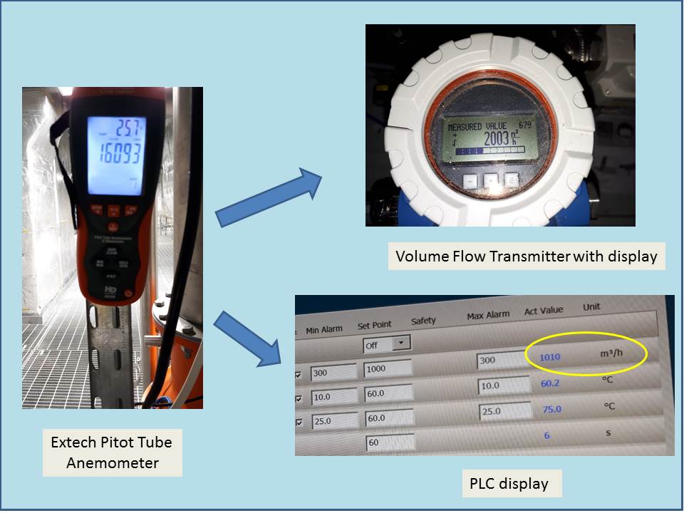
Calibration is done by comparing the readout taken from the pitot tube to the display of the volume flow transmitter or PLC.
Materials and equipment:
- Extech DH350 Pitot Tube Anemometer – the main reference standard
- Thermo-hygrometer – to record temperature and humidity
- Unit Under Calibration (UUC) – airflow transmitter or PLC display
- MDS (Measurement Data Sheet) – to record all necessary UUC details and calibration results
Calibration procedure:
- After completing the setup, let the Standard and UUC stabilize in the environment for at least 15 mins.
- Make sure the pitot tube is in the middle of the duct and facing against the direction of the wind. If the wind is going down, the tube is facing up. (see photo). Use the ruler that is printed on the tube to ensure that it is in the middle of the pipe.
- Make sure the pitot probe is in the correct position (not tilted or turned) and stable to avoid errors.
- Ensure positive port are in the Impact pressure port of the tube and Negative port on the static port of the pitot tube to have a correct reading.
- Set the desired range of the airflow.
- Generate the airflow, wait for the readings to stabilize and compare the readings.
- Perform the next range as per customer requirements
- Record your reading in the MDS (Measurement Data Sheet)
Verification- How to Verify the Air FLow Accuracy in the Duct.
After calibration, we can now verify the volume flow if it is within the tolerance specified by the manufacturer or set by the user.
How to verify the volume flow? We will use the calibration result and compare it to the tolerance specified by the user.
For example:
Tolerance specified = +/-50 CMH
Calibration result:
Set point: 1000 CMH
UUC reading: 1010 CMH
STD reading: 1015 CMH
Error = -5 CMH
Therefore: it is passed, 5 CMH is within the +/- 50 CMH tolerance
Conclusion
In this post, I have shared with you the following:
- The basic principle of a Pitot Tube.
- How to Setup Pitot Tube for velocity and volume flow measurement in a duct or pipe
- Using a Pitot Tube Anemometer to calibrate and verify the Velocity and volume flow reading of a flow transmitter in a duct
The usage is very simple, you just need to have a careful setup or alignment in order to achieve more accurate results.
Thank you for visiting my site, please comment and subscribe
You can also connect with me on my Facebook page.
Best Regards,
Edwin
7 Responses
Christopher Rodil
Helo Edwin,
Very interesting subject that you have been shared to us..im not expert in flow calibration but in this the way the calibration procedures help us to perform easily in the field and reduces the time in actual calibration.
Keep in touch with us sir Edwin so that many ice and ict gain additional knowledge from you. God Bless more power.
edsponce
Hi Rodil,
I appreciate your comments and I am glad that you like my post that it helped you in some way.
Best Regards,
Edwin
Nisha Mehta
A must-read guide for flow calibration services! flow calibration services
Patrick
Do you make the Static Pressure and Top pressure tubes equal lengths to manometers or differential pressure transducers?
Will that alter the calibration if one is shorter than the other?
edsponce
Hi Patrick,
They have the same length but I did not consider the length of the pressure tubes. I did not experience it yet if there is an effect if you vary the length of the tubes. There is an observable effect if you vary the position of the pitot tube.
Best regards,
Edwin
Valmik Patel
I’ve been reading about this since its relating to my niche. Thanks a ton to share this.
edsponce
Hi Valmik,
You are welcome. Thanks for visiting my site.
Edwin