In my last post, I presented how to calibrate a clamp meter using a Fluke 5500 standard coil to amplify a current simulated from the Fluke 5522a. You can attain the required current output by using the standard coil.
A Clamp meter is used by clamping it on a current-carrying conductor in order to check the current without breaking or opening a cable.
In this post, I will show how to verify a clamp meter using only a simple current conducting wire (a standard coil is required for calibration). You will also discover here how a clamp meter measures a high current value in a coil of wire.
We will only focus on the current function of the clamp meter which is its basic application. Ok, let us start by following the photos below.
.
Verifying a Clamp Meter zero reading
I will use a single line of cable (a connector) to demonstrate the verification process. We will still need the Multiproduct calibrator as our source of current (dc).
If you have other instruments or calibrator that generates current with a known value, like a calibrated power supply, it will also do. Or if you have 2 pieces of a clamp meter, in which one is calibrated, you can use it as the reference to compare reading.
Starting in figure 1 below, notice that Fluke 5522a is generating a current but the reading is zero (0), why?
Zero reading means there is no current flowing in the conductor. But in a clamp meter, this is not always the case.
A zero reading can also happen if you measure a conductor simultaneously that has an opposing flow of current, meaning the direction of the current is different, one is going down while the other is going up. This happens when a pair of conductors are clamped together.
Based on figure 1, notice that the red and black cable has the opposite direction of current flow, so the net current becomes zero.
The lesson here is to measure a conductor only in the same direction of flow or polarity. We need to separate the two wires and measure only a single wire to attain a single direction of the current flow.
Figure 1.
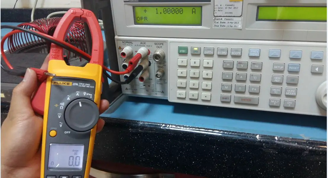
Verification of Current From a Single Conductor.
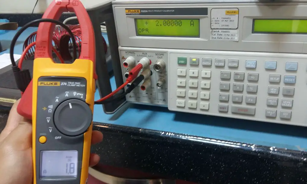
Now, based on Figures 2 and 3, I separated the red wire and clamped only the black wire. Then simulated current of 1 A and 2 A. As you notice, it is already having a reading. The standard simulated current reading from Fluke 5522a is compared to the reading of the clamp meter.
As you also observe, one piece of wire will only read exactly the value of the simulated current, at a 1:1 ratio. But by using a multiple piece or coil of wires, we can increase the value of the current without increasing the current value.
See figure 4 for this presentation.
.
Figure 2.
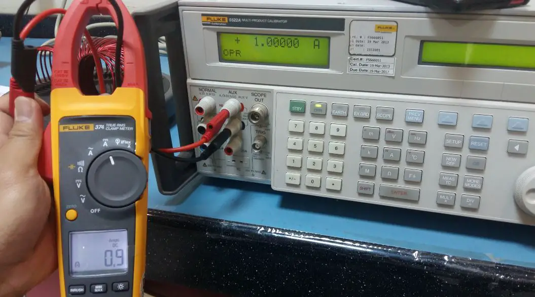
Figure 3.
.
Verification of Current from a Multiple Conductor (How Current is Amplified by a Coil of Wire – The Principle of a Current Coil).
If you have a limited current source but you like to increase the value of current to be verified and measured, what you can do is to increase the number of coils, turns, or windings where the clamp meter will be clamped-on.
Increasing the number of windings or coils (also known as turns) will also increase the current reading. The value of the current multiplied by the number of turns.
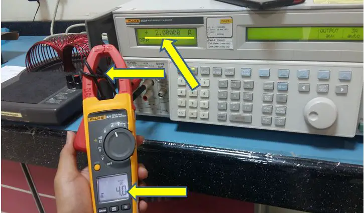
Based on the figure below, notice that I increase the number of windings in the black wire, (becomes 2 coils). Observe that I have a current of 2 A but the clamp meter displays a current of 4 A.
The Ratio of the current to wire becomes 1:2. Any current value will be amplified by a factor of 2.
You can increase more the value of the current by increasing the number of turns in the conductor. This is the principle of the Fluke 5500 standard coil where it has a 50 turns coil. Any current that passes through that coil will be multiplied by a factor of 50. It has a ratio of 1:50.
Figure 4.
Please note that this is only a simple presentation, in order to have a more accurate result, the coiled wire should be positioned in the middle of the clamp or jaw of the clamp meter.
.
Conclusion
This is how we can verify the accuracy of a clamp meter without a standard coil. You can use this set up if you do not have a standard coil. I have shown you how a number of turns of wire can amplify a current value. The wire I use here is limited in length but in order to have a more accurate reading, make sure that the conductor that is coiled or being clamped-on is in the middle of the clamp meter jaw.
For more details on how to calibrate a clamp meter, you may visit my other post here.
Thank you for visiting my site, please comment and subscribe.
Edwin
8 Responses
Naveed Ahmed
thanks for good information
edsponce
Hi Naveed,
You are welcome! Thank you for reading my post.
Thansk and regards,
Edwin
Steve
Hi,
Great article on current clamp calibration. I was wondering where would I find a calibration guide for a Snap-On EETA503C Low Current Probe? I tried searching on the internet but couldn’t find on.
Thanks
edsponce
Hi Steve,
Thank you for reading my posts. Usually, The manufacturer’s manual is the best guide for it. You can also use other manuals with the same characteristics like Fluke manuals. I have another related post on clamp meter calibration that is based on the Fluke calibration procedure. Read here if you have not seen it yet.
You only need a stable reference current to perform the calibration for the Snap-On EETA503C Low Current Probe. You can try the example that I just presented above using a single wire that is coiled together.
I hope this helps,
Edwin
Manuel M. Ruiz
The method of winding the current carrying wire on the jaws of a clamp meter to simulate a higher current is technically valid. For calibration purposes however, one should exercise some caution on its use. The reason Fluke goes to great extent to design their current coil is for proper positioning of the magnetic flux produced by the coil with respect to the measuring jaws of the current clamp (among others). You would observe that clamp meters have some alignment marks/guides to properly position the current carrying wire to achieve its specified accuracy. Merely winding turns of wire around the jaws may not be enough to assure meeting specifications of the clamp meter under calibration.
edsponce
Hi Manuel,
I agree with you. Thanks for sharing your thoughts.
With caution and proper positioning of the clamp meter jaws on the created turns of wires, one can attain a good setup to verify the accuracy of the clamp meter. This is not advisable as a calibration procedure but can be used for intermediate check purposes.
Thanks for visiting my site.
Edwin
Marian
Thanks for sharing this useful information. Same with you, I also using Fluke clamp meter for a years. Everything is good about this product.
edsponce
Hi Marian, You are welcome.