In my past post, I have presented how a multimeter is being calibrated or verified using a multiproduct calibrator, and in this post, I will present with you how a clamp meter will also be calibrated.
These 2 are somewhat related, having knowledge in calibrating a multimeter will give you a good idea on how to calibrate a clamp meter, because clamp meter nowadays is also designed with the functionality and capability of a multimeter.
As I explained, calibration is the verification of the accuracy of a measuring instrument, calibration does not need to be adjusted.
We will just compare the reading from a standard source which is the calibrator (also known as the reference standard) to determine how far its reading was from its true value.
Adjustment is based on the skill and knowledge of the technician and it is a plus if you know it.
What is a Clamp Meter?
A clamp meter is specifically designed to measure currents in a current-carrying conductor or cable, also called a clamp-on ammeter ( see wiki) or sometimes clamp ampere.
It is designed to measure a large number of currents usually 500 Ampere AC to a thousand values, which is not normally measured by an ordinary multimeter.
The best thing in using a clamp ampere meter is that you do not need to open the cable or cut into it just to measure the current. As the name implies, just clamp it on the wire and you’re ready to measure. It has also an advantage of safety and there are no interruptions of work because you do not need to cut or open wire.
Where Do We Usually Use a Clamp Meter?
Clamp meters are usually used in a high voltage high current environment like a power plant, AC motors, HVAC or any current-carrying conductor that has high ratings of current for troubleshooting and monitoring.
But nowadays, the capability of a clamp meter is almost the same with a digital multimeter where it can also measure resistance, voltage, and frequency which is basic to a multimeter. So how it is being used can now be compared to a multimeter when it comes to industry troubleshooting and monitoring.
How to Calibrate a Clamp Meter?
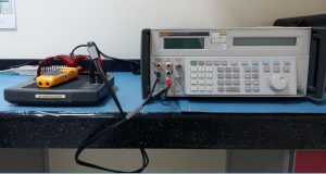
A simple demonstration on how a clamp meter is calibrated using a multiproduct calibrator (Fluke 5522A)To learn more about the calibration procedure, visit this link..http://bit.ly/clampmetercal
Posted by Calibration Awareness on Thursday, October 25, 2018
Some mistakes can be seen in the video, please make sure to put to standby mode first before changing range or settings to avoid the possibility of damage.
This procedure is presented specifically for Fluke clamp meters ( Manufacturer: Fluke, Model:321/322/333/334/335/336/337). But it is also applicable to most clamp meters with other manufacturers. Verification is almost the same with the multimeter in most parameters. So we will also expect to calibrate the Voltage, Resistance and Frequency functions. You may visit this link to see how a multimeter is calibrated.

Objective:
To define the verification procedure on digital clamp meters using Fluke 5522A Multi-product Calibrator as the reference standard with Fluke 5500A coil as the current amplifier.
Calibration Method:
This is accomplished by comparing the electrical signal generated by Fluke 5522A, which is the reference standard.
Requirements:
- Warm-up time (UUC): At least 1 hour for proper stabilization
- Temperature: 23 +/- 5 deg C
- Humidity:50 +/- 30%
- Perform 5 test points for each range
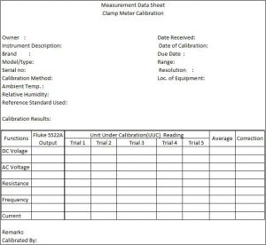
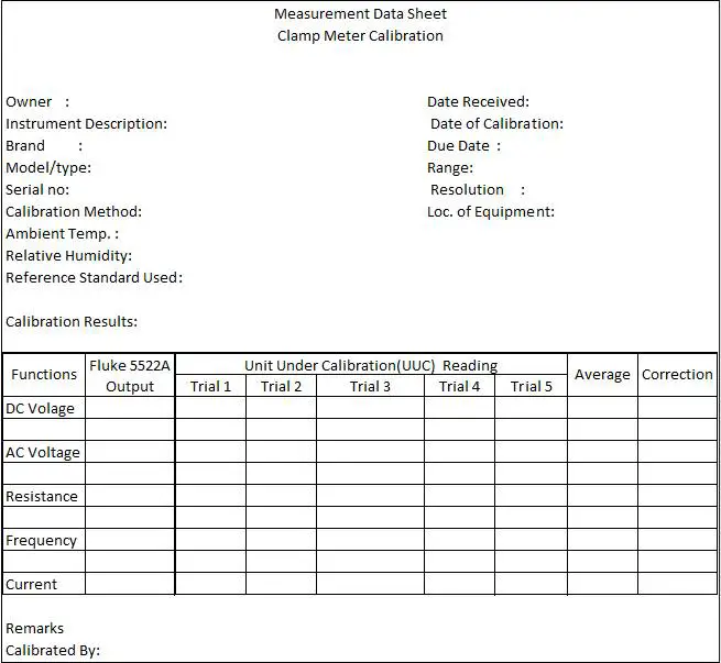
- Measurement Data Sheet (MDS) (Check this link to learn more about Measurement Data Sheet)
Reference Standard and Equipment:
- Fluke 5522A Multi-product calibrator
- Fluke 5500A Coil -a coil of wire (50 turns) used to amplify a current to 50 times for a higher current
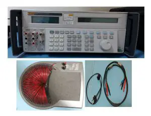
5522A, Coil and connecting leads requirement usually above 20 A. (output of 1 Ampere by the calibrator will be amplified to 50 A by the coil in which the clamp meter will read)

- Thermo-hygrometer – for monitoring temperature and humidity
- Connecting Leads/wires
Calibration Procedure:
1. Check the Clamp meter for any visual defects that can affect its accuracy including its display by turning it power ON. Discontinue calibration if any defect is noted.
- For Fluke 321 and 322 models, test display by turning the UUC ( Unit Under Calibration) ON while holding down the HOLD button.
- Check all segments for clarity and contrast.
- For 334-337 models, test display by turning the UUC ON while holding down the INRUSH button. Check all segments for clarity and contrast. Model 333 is not equipped with this feature.
- Hold Button Testing (for Fluke 321 and 322 only):
- Turn the UUC ON and push the hold button. Each button push will cause the meter to beep.
- Keypad Test (for Fluke 333-337 only):
2. Clean the Clamp meter with a soft cloth, Check if it has good batteries, replace low powered batteries.
3. Allow a stabilization of 1 hour, to be conditioned on the environmental conditions of the room.
4. Prepare the Measurement Data Sheet (MDS) and record all necessary details or information ( Brand, Model, serial #, etc).
5. Determine the parameters and test points to be calibrated on the Clamp meter, choose at least 5 test points. Record this on the MDS.
6. Using Fluke 5522A, connect the necessary test leads to measure DC Voltage, AC voltage Resistance, and Frequency. Just like calibrating a multimeter, the connections and procedure are the same in terms of connections and key functions of the Fluke 5522A.
7. DC Voltage Verification:
- Connect VΩ terminal of the UUC to the NORMAL Input HI of the Fluke 5500A calibrator and the COM terminal to the LO Return side.
- Set the rotary switch of the UUC ( Unit Under Calibration) to DC Voltage mode.
- Press the numeric key of the 5522a calibrator to each of the required voltage setpoint values shown in Tables 1 or 2 below ( These are actual limits taken from its manual, for other models, please check its user manual from Fluke)
- Wait for the display to stabilize ) then get the reading. Record readings on the MDS.
- Take note of the measured value on the clamp meter.
8. AC Voltage Verification:
- Position the rotary switch of the UUC ( Unit Under Calibration) to AC Voltage mode.
- Press the numeric key of the 5522a calibrator to each of the required voltage setpoint values shown in Tables 1 or 2 below. ( These are actual limits taken from its manual, for other models, please check its user manual from Fluke)
- Wait for the display to stabilize ) then get the reading. Record readings on the MDS.
- Take note of the measured value on the clamp meter.
9. Resistance Verification:
- With still the same connection position the rotary switch of the UUC to Resistance mode.
- Press the numeric key of the 5522a calibrator to each of the required resistance setpoint values shown on Tables 1 or 2 below.
- Wait for the display to stabilize then get the reading. Record readings on the MDS.
- Take note of the measured value on the meter.
10. Frequency Verification (for 337 only):
- Position the rotary switch of the UUC to Frequency mode.
- Press the numeric key of the 5522a calibrator to each of the required frequency setpoint values.
- Wait for the display to stabilize ) then get the reading. Record readings on the MDS.
- Take note of the measured value on the meter.
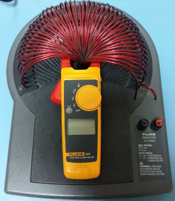
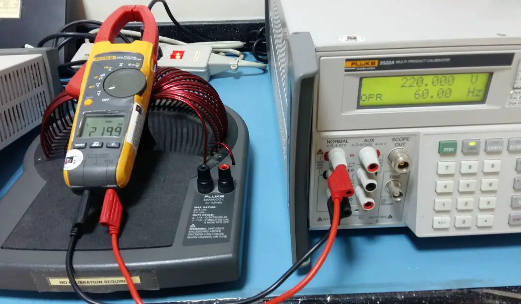
11. For AC/DC Current Verification, we will now use the Fluke 5500A coil. Clamp the clamp meter on the coil, make sure it is positioned straight or flat at the middle of the coil for better accuracy.
12. AC/DC Current Verification: Remove all connections from the UUC.
- Connect the Fluke 5500A coil to the Fluke 5522A calibrator and clamp the UUC to the toroid coils of the Fluke 5500A coil as illustrated in the Figure.
Clamp meter Current Function Calibration Setup - Note that for a current above 20A, transfer the HI lead wire to the 20A – terminal.
- Position the rotary switch of the clamp meter to the proper AC/DC Current mode.
- Press the numeric key of the 5522a calibrator to the required setpoint value as shown on Tables 1 or 2 below.
- Wait for the display to stabilize ) then get the reading. Record readings on the MDS.
- Take note of the measured value on the clamp meter.

13. Check readings if within the accuracy defined by the manufacturer, for example, accuracy = +/-2 of reading. See the related table.
14. If the readings are already within limits update the corresponding record, do labeling and sealing and issue to the owner, otherwise, do necessary repair or adjustments.
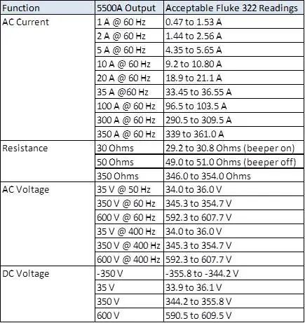
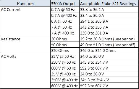
Table 1. Fluke 321 Performance Verification Test Limits
,
For the list of Clamp meters, please click this link clamp meter.
…
How to perform clamp meter adjustment?
If in any case, you need to adjust the Fluke 376 clamp meter, download its calibration manual which is also provided by Fluke. Click this link >>> Fluke 376 adjustment procedure
End of Verification
…
Conclusion
I have presented here the calibration procedure of a clamp meter using the reference standard Fluke 5522A and a coil. The coil is used to amplify the current needed by the clamp meter.
A clamp meter is used in a wide range of high current measurements without opening or cutting the wire. The procedure is based on the manufacturer manual so anyone can use directly the limits or tolerance presented.
The next step after the data was gathered and recorded in the MDS is to create the calibration certificate.
Do you need a guide on what to include in a calibration certificate? How to review and interpret the content of a calibration certificate? How to use it properly during calibration or maintenance? Check the link below
Visit here: how-to-properly-use-and-interpret-an-iso-17025-calibration-certificate
What if you do not have a standard coil? Check the procedure here>> How to Verify the Accuracy of a Clamp Meter without using a Standard Coil?
Thank you for visiting my site, please comment and subscribe.
Edwin
10 Responses
Vinod
Dear Sir,
Thanks for your valuable post. I am regular reader of your posts.
Requested you to guide us to prepare quality manual for ISO 17025:2017. Please post something about it.
Thanks
edsponce
Hi Vinod,
You are welcome and I appreciate your time for reading my posts.
I have created a guide as per your request and hope that you like it.
Please visit this link.>> https://calibrationawareness.com/iso-iec-170252017-requirements-list-of-documents-outline-and-summary
Appreciate your feedback.
Thanks and regards,
Edwin
Thanks and regards,
Godwin egurudu
How do you adjust fluke 376 when the readings is not within the limit of accuracy for the various functions
edsponce
Hi Godwin,
Fluke has a service or calibration manual wherein they provide on how to adjust the meter. Please see below link for the calibration manual
>> Fluke 376 calibration manual
Thank you for reading my post.
Thanks and regards,
Edwin
afan raza
very nice post
edsponce
Hi Afan,
Thank you. I am glad you liked it.
Edwin
odell
what about the I-flex?………………………..nothin?
edsponce
Hi Odell,
It has the same procedure and principle with the main clamp when using the I-Flex. Just make sure to read its manual for the specifications and proper use.
Edwin
Naaz
Hi, Please advice what are the uncertainty budget components for estimating the expanded uncertainty for clamp meter.
edsponce
Hi Naaz,
there are no exact uncertainty budgets but below are my recommendations as a minimum:
1. Repeatability of UUT reading (TYpe A)
2. Resolution of clamp meter
3. Uncertainty value of the STD from its calibration certificate
4. Stability of the reference standard
5. Accuracy of the current coil
6. calibrator resolution
I hope this helps,
Edwin