I was messaged by one of my reader about a question related to my previous post about “How to Interpret a Calibration Certificate”. See the post here. It is a good question because I did not cover it on the previous post and it is a good thing to discuss and share it with you.
I believe that someone out there also needs this answer and I hope that it could help.
And here is His actual questions:
- “How do we know either this caliper is fit to use or not based on this statement & the calibration result?”
- “What shall we do with the instrument when we received the certificate with this mentioned statement?” Below is the remark with a photo.
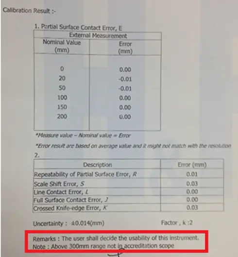
“Below is a calibration certificate for my digital caliper & there is a remark stated as”
‘The user shall decide the usability of this instrument’.
Now, let us discuss…
First Question:
How do we know either this caliper is fit to use or not based on this statement & the calibration result?
Or another related question is, “How can we perform verification based on the given calibration results?”
Passed or failed remarks are usually termed in calibration as “In-Tolerance” or “Out-of-Tolerance”. This is not usually displayed in most calibration certificates if it is not relevant, appropriate, or requested by the user.
Some calibration labs displayed a tolerance limit but they will include in the remarks that the tolerance used is for reference only.
Why? Because an out-of-tolerance condition is only determined and decided by the user of the instrument. His decision could be from a process requirement or an international standard requirement.
The lab will only reflect the result, and based on this result, it is up to the user to decide its suitability or acceptability if still fit to use.
Any tolerance that will be reflected in the certificate should be agreed first with the customer. And in any case, if an Out-of-Tolerance condition is observed, it will be reflected in the calibration report but the customers are first informed.
But If tolerance is not provided, how can you determine or decide if your instrument is still fit for use (or not) based on the calibration result?
Read further…
Below are 3 ways to determine and verify if your instrument is fit to use or not based on the calibration certificate. Just choose one where you are comfortable and very much applicable to your process.
- Determine your process tolerance;
- Check the specifications of the instrument in the user manual;
- Use the uncertainty results.
I will explain further in more details….
3 Ways To Determine and Verify the UUT Tolerance with a Calibration Certificate (Calibration Certificate Verification Procedure)
First, refer to your process tolerance, it is determined during the design of your measurement process (it should be available).
During calibration, the lab will determine how accurate the caliper is by basing it on the reference value. By having a reference value, an error (Measured value-True Value) will be computed and reflected in the calibration certificate.
For example, in a caliper, the error displayed in the calibration certificate during the calibration on the 20 mm range is +0.06 mm.
If the user has a tolerance based on their process which is +/-0.04mm, then, this means that it is already “out-of-tolerance”.
This kind of instrument is non-adjustable that is why you will rely on the result and use a correction factor just in case.
For more details on how to use a correction factor in a calibration certificate, visit this link.
Second, check the specifications of the caliper in the user manual, look for the accuracy specification, and get the value (you need a little research).
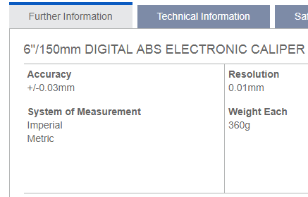
Again, determine the error displayed in the calibration certificate. Compare results if the 0.01 error (based on the sample certificate above) is within the accuracy range of the caliper (which is 0.03 in the above photo).
As per the result of the comparison, 0.01 is within the limits of 0.03 so it is in “Tolerance” or fit for use.
THIRD and final, check the uncertainty results. The uncertainty result is the combination of all or most of the possible sources of errors that the caliper can receive or encounter.
So you can make the uncertainty result as the basis for tolerance. If the readings of the caliper are within this uncertainty value, then it is a good measurement and the caliper is still fit for use.
Since uncertainty results are usually very small, that will result in a strict tolerance, the possibility of a failed result is higher.
What you can do is to multiply the uncertainty results by a factor of 2 to expand it to a 95% confidence. Ensure to document this procedure to support an audit question just in case.
![]()
based on the above result, the tolerance would be:
tolerance = 0.014×2 = 0.028 mm or 0.03mm
You can do any one of the above check items as part of your quality control. For me, the easiest is to use the second option because that is already the capability of the instrument based on manufacturer’s recommendation, but it is still up to you as long as it is properly documented and aligned in your process.
Check my other post here where I explained in detail the related calibration terms>> Differences Between Accuracy, Error, Tolerance, and Uncertainty in a Calibration Result
2nd Question:
What shall we do with the instrument when we received the certificate with this mentioned statement?
‘The user shall decide the usability of this instrument’
Every calibration lab is required to put their remarks based on their opinions and interpretations once calibration is already performed and results have been provided.
The above statement means that the suitability of using the instruments is now into the user that He/She should make a proper decision based on the provided result by the lab.
And this is because only the user is the one who knows where to apply the given calibration results based on their day to day process, that is why “the user shall decide the usability of the instrument” but in consideration to the results in the calibration report.
So how do we decide the usability?
Below are my suggestions:
1. Review the results and see if it is within your applicable tolerance or specifications (refer to question number 1 answers).
2. Ensure that when using the calibrated instrument, the range used or calibration points should be aligned on what is reflected in the calibration certificate results.
2. Use the indicated correction factor or compensate for the error using the correction factor every time you use the UUC for measurement.
3. Perform a functionality check once received from the cal lab. Read more below..
What can we do after we received the calibrated instrument?
In addition to the determination of tolerance in the calibration certificate, there is a mandatory procedure that we need to do during the receiving process.
Every measurement result provided by the calibration lab is taken inside their laboratory which means that it has different environmental conditions, etc.,
Once the instrument is brought back into your facility, it is now exposed to different environments and handling. Moreover, there is a tendency that a mishandling or some outside factors like vibrations or accidental drop may occur.
Also, once the Instrument is released, it is now up to the user to determine the validity and the usability of the instruments as stated in the calibration certificate remarks.
So during the receiving process, or upon receipt of the instruments, make sure that you handle this properly and use the appropriate procedure for quality control to verify that it is still in good condition.
Also as an SOP for quality control check regarding the instruments that are shipped back to your company after calibration, perform what we call a functionality or intermediate check.
Even it is newly calibrated, the handling as I stated above, during the transport can have an effect on its calibration, therefore it is mandatory to perform a functionality check once you have received the caliper.
Use a known sample, with a known data, where the caliper is being used before it was shipped out for calibration and measure it again. If the result is within your expectation then it is ok.
Do not forget to document this. You may also include in your documentation on how you perform a review or assessment regarding the calibration certificate.
( learn more about the functional check or intermediate check in this link Intermediate Check)
Additional concern…
The NOTE: “Above 300mm range not in accreditation scope “
During accreditation, the accreditation body will check all your capability and reflect the result on the scope of the accreditation certificate.
In this case, 300 mm range is not included in that scope. This means that the lab is not accredited to perform the calibration.
Before you give the calibration work to a lab, or before calibration takes place for your caliper, you should be informed in any way and have your approval or agreement from them.
This is an SOP as an Accredited Calibration laboratory but sometimes you need to ask or inform them.
There is no problem here if you are not using that range, or it is not that critical that you can support during an audit.
I hope that I answered your questions, please do not hesitate to answer me back if you encounter any more concerns about my blog post.
Conclusion
An ISO 17025 accredited calibration lab follows the format of an accredited calibration certificate requirements. It is a must that a calibration lab will provide remarks regarding the observed parameters during the calibration process and reflect it on the certificate if those remarks support a certain measurement result.
I have discussed in this post about the remarked ‘The user shall decide the usability of this instrument’, provided the “3 Ways To Determine If The Instruments is Within the Tolerance based on a Calibration Certificate” and answered the question ‘What shall we do with the instrument when we received the certificate with this mentioned statement?’
If you have determined your acceptable instrument tolerance and the correction factor to be used, then I can say that you have already determined the usability or suitability of your instrument for your intended use.
For more details on what to review on a calibration certificate requirements, visit this post: How to Properly Use and Interpret an ISO 17025 Calibration Certificate
Do you have other ways on how to determine tolerances or how to determine a Fit or No Fit status of an instrument based on its calibration certificate?
Please do not hesitate to comment.
And do not forget to subscribe and share.
Best Regards,
Edwin
13 Responses
Hemal Kateliya
Sir can you explain the same thing about a dial gauge with 10mm range and 0.010 mm least count.I have question that will deciding whether my dial gauge is acceptable for use or not what should check out of max downward error ,max upward error or hysteresis ..
edsponce
Hi Hemal,
Do you perform calibration or just a user of a calibrated dial gauge?
If you are a user, you just need to have your dial gauge calibrated and use the results in the calibration certificate.
In order to determine if it has an acceptable reading, you need to compare its reading to your tolerance. Do you have a set tolerance during the measurement process? If it is within your set tolerance then it is a passed or acceptable.
If you have the necessary reference standard to perform the calibration, like a micrometer head, you can perform different tests or verification to determine the error and decide if it is acceptable or not.
One standard to follow is the JIS B7503, it will show you the MPE (Maximum Permissible Error). These are the tolerances that you will follow.
For your case, below are the MPE(+/-) for a 10 mm range with 0.01 resolution:
> Hysteresis (retrace) error = 3 um
> ½ revolution (equivalent to 0.5 mm) = 9 um
> 1 revolution (equivalent to 1 mm) = 10 um
> Full range (10 mm) = 15 um
If your measurement results are within this MPE, then it is acceptable.
In order to determine the hysteresis error, my suggestion is to perform the whole range of increasing and decreasing points (same test points for increasing then decreasing), get the difference (test point 1 inc – test point 1 dec) then choose any range that displays the maximum error.
I get this MPE in the 2011 version of the standard. You may want to check the latest version if it is available.
I hope this answers your concern.
Edwin
Robert
Excuse me by chance you know how you can determine the frequency of recalibration of thermohygrometers and if you have a much better example. Thank you
edsponce
Hi Robert,
The frequency of recalibration has no specific requirements. It is based on the user’s experience or the recommendation of the manufacturer. But the most is from the user’s experience. As a suggestion, I will share with you the reply that I have given on my other post. They are related where I believe this can help. Below is my response with an example from intermediate check results.
“Since you already have the past records or history, you only need to show the performance of the reference standards by using the control chart.
Stability is determined by collecting data on a fixed interval. In can be daily, monthly or every 3 months.
Our main objective is to determine if the encountered drift is acceptable. Drift is the variation of the performance over time which can be observed as an error. Drift can be detected through the calculated error which can be related to stability that can be observed by plotting the errors in a control chart.
What I always use for analysis and presentation is the control chart. You can do this easily in excel. See below example:
I have collected data through an intermediate check performed every three months on a Test Gauge.
Below are the data.
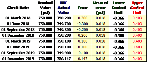
Intermediate Check Results
Determine the error, calculate the mean, and the standard deviation
The formula from excel:
Excel formula for Control Chart
The plot in the control chart.
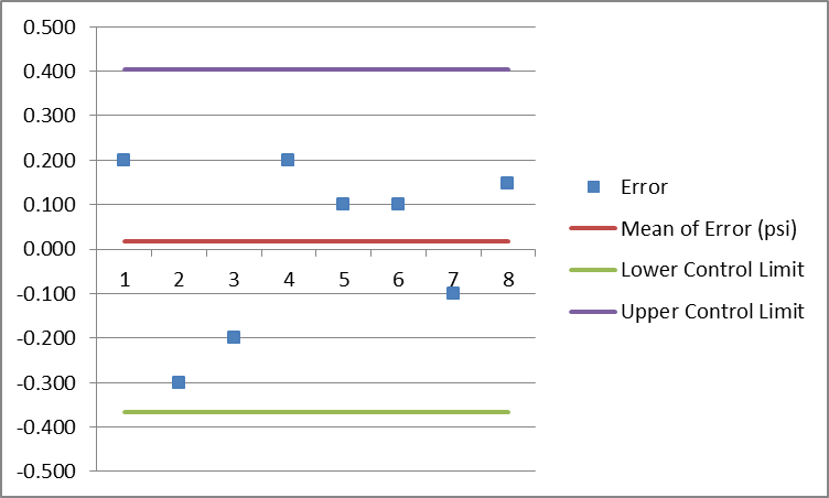
Control Chart for Stability
As long as the error is within the control limit, we can be sure that the reference standard is very stable and in control.
My suggestion is that in addition to the intermediate check for calibration interval analysis, it is best to include the results in a calibration certificate every time the reference standards are brought back from calibration.
Gather the data and use the same principle that I have presented. This will show you that for example, during the 3 years period of calibration performed, where you will observe based on the chart that the instruments are still stable.
Therefore, you can extend the interval for 3 years since you have the evidence of its performance within a 3 year period.
You can also include in your analysis its accuracy performance through the use of manufacturer specifications as the control limits or tolerance.
This simple method is acceptable as per my experience, but if you want to have a deep or more detailed analysis, there is a statistical tool called Minitab, I did not try it yet but I suggest you check it.
This can automate the process of data analysis which includes the control chart, repeatability, reproducibility, trend analysis and a lot more.”
I hope this helps,
Thanks and regards,
Edwin
Marcella
Allow accuracy variations of up to 0.001 inch in the first 4 inches of the caliper, 0.0015 inch in the 4- to 8-inch range, and 0.002 inch from 8 to 12 inches. Mentally compensate for the variation in any measurements. I was wondering if this statement is true. I tried to look it up on the N.I.S.T web cite.
edsponce
Hi Marcella,
Is that a manufacturer’s specifications? Try to read ISO 13385-1:2019 standard, I believe this supports the statement. Look for the MPE part.
I hope this helps,
Edwin
ravi
Hi Edwin, You have taken the Average Mean from Error and you making SD*2 for upper and lower limit. so your error will always be within the sd*2 only since this SD also you have taken from the error. Instead of that you should make the instrument accuracy to determine the drift of it
Vinod Kumar
Hi Mr. Edwin, Good Morning!
Can you share complete draft report of Digital Vernier Caliper as per IS 16491, In existing, we were referring IS 3651 which is replaced by IS 16491. Special interest in MPE.
edsponce
Hi Mr. Vinod,
Good day! Sorry but I do not have the entire report, that is the only part I have that is shared by one of the readers here. But the reference document based on the requirements seen in the report is from ISO 13385-1:2019. 2019 version has the additional MPE recommendations that you can use.
Thanks and regards,
Edwin
ken
Hi Sir, regarding the calibration of a caliper, is there a standard measuring length for a certain range of a caliper, for example, I have a 200mm caliper, on what lengths do I need to conduct measurement? How many measuring lengths do I need to check, e.g 20mm, 50mm, 100mm, 200mm.
edsponce
Hi Ken,
Yes, there are, your example is ok. But if you are following the ISO 13385-1:2019, for a 150 mm range, you can 5 calibration points across the measuring range of the caliper. For 300- 6 test points and for 1000- 7 test points.
The caliper calibration points are up to you, but the considerations are:
1. At least 1 test point is in the 90% or greater of the measuring range
2. 1 test point near the beam
3. 1 test point near the tip of the jaws
This test for caliper is called the partial surface contact error.
There are other tests like shift errors. You need to read ISO 13385-1 for more details.
I hope this helps,
Edwin
Rahmah
Hi Sir, I’d like to ask you regarding your statement about this “What you can do is to multiply the uncertainty results by a factor of 2 to expand it to a 95% confidence. Ensure to document this procedure to support an audit question just in case”.
Can I equalize this to all kinds of tools/ instruments? I mean every single things that calibrated may have its uncertainty, then I just multiply by 2.
Another question, can user generalize the acceptance of that into each parameter? even they may come from type etc.
Thanks in advance
edsponce
Hi Rahmah,
Yes, you can implement this to all kinds of instruments with calculated measurement uncertainties as part of your quality control. But this kind of method in determining tolerance limits sometimes resulted in a very small or very large value which you need to analyze if it is acceptable in your process. It may be too tight or too wide.
Some reason for this is that different labs provide different uncertainty results depending on the accuracy of the standard and the procedure they used during calibration, therefore it is important to check first the CMC (in their scope of accreditation) of the lab prior to accepting calibration from them.
For me, I only use this method if the accuracy is not given by the manufacturer or there is no other basis to determine the tolerance limit of the instrument.
Thanks for visiting my site.
Best Regards,
Edwin