Have you ever wondered why the cables on your appliances are safe to hold while plugging it into the electrical source? Or the electrical lines going into your house does not shock you every time you touch a metal post or every time it is wet?
This is because the conductors are properly insulated. But any leak or shortage in these electrical wires can cause shock or damage to appliances.
That is why every unit or appliance supply wires, building electrical connecting wires, or electric motor cables need to be tested first for proper insulation before they are released for public use. This is where an insulation tester is being used.
Insulation testers are used to check and detect if there is a leak of current in a conductor or other electrical components. And the most commonly used Insulation tester is the Megger Tester (a brand and a company name).
For most people, once you say Megger, it is automatically an insulation tester. But we should also know that Fluke has its own Insulator Tester which is the Fluke 1507 insulation tester.
In this article, I will share how to check and verify the accuracy of your megger tester in measuring a resistance value that you may implement before using your Megger. Also, it includes the verification of the output voltage to ensure that you have a reliable reading.
Furthermore, I will also present a calibration procedure that you can implement for your in-house calibration just in case you have the necessary reference standards which I will present here. In this post, I will be using the Megger BM11D.
What is an Insulation Tester?
A multimeter can be used as an insulation tester but in a limited way, mostly as a continuity test and detecting the presence of a current or voltage only in normal conditions. If there is no flow of current in an insulated wire when tested, it means that the wire is safe to hold.
But what if there is a break in the insulation and a high voltage or current will pass through it? Surely, the wire will get burned or create a short circuit that can cause damage and fire. This cannot be detected by a normal multimeter. There is an accident waiting to happen.
In order to detect and test for a leakage current during a normal or overloaded condition, we will use a special instrument known as the Insulation Tester like Megger.
Functions of an Insulation Resistance Tester: Principles of Operation
- The main function is to test the insulation of a set of conducting wires by measuring the resistance. In this sense, this tester is also called an Insulation Resistance Tester. The higher the resistance reading, the better. Usually in Mega Ohms reading. A lower value of resistance means that there is a short or leakage of current causing the resistance to drop.
- Used as a voltage source to test for the integrity of the conductor. An insulation tester has the capability to source out or generate a high amount of voltage. This voltage is injected into conducting wires to test if the insulation can withstand the high voltage. An insulated conductor can have a normal reading in a low voltage value but during exposure to a high voltage, the insulation can break and leakage may occur.
- Function as a continuity tester. Testing for continuity on a very long cable or wire cannot be guaranteed by a simple multimeter. Because of the high voltage generated by the insulation tester, you can measure a significant amount of resistance.
- High resistance (infinity) reading means open while a zero or very low resistance means short. But no need to record because most Insulation tester has an audible alarm for short or open status.
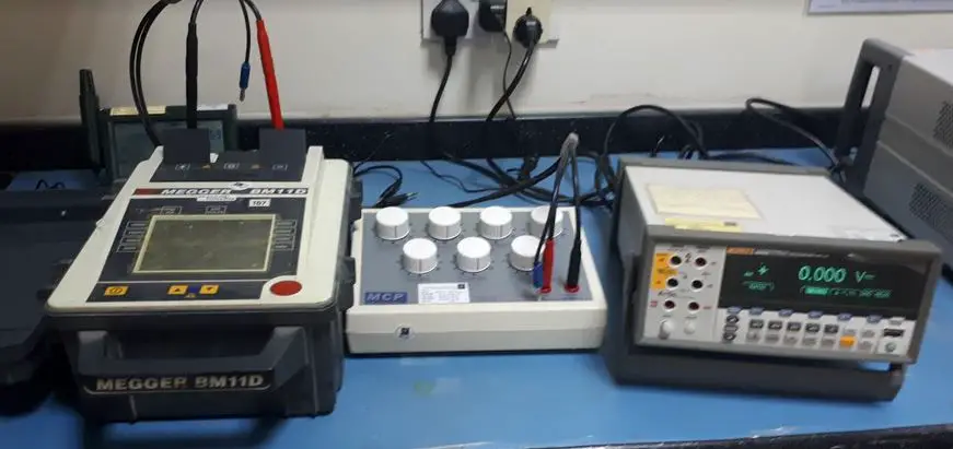
How to Use Megger Tester- Accuracy Verification Setup
Since we already know the working principles of an insulation tester, I will show you how to verify the accuracy of your Megger Insulation Tester by using a resistor and a multimeter. Learning how to use the Megger Tester leads to an easy understanding of its verification procedure.
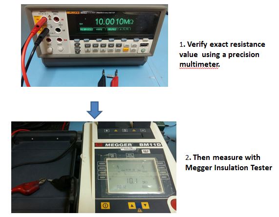
Resistance Function Verification
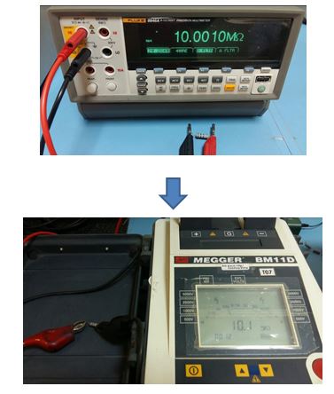
Since this is an insulation resistance tester, just directly measure a resistor with a known value (Please see the figure below). If you want to record a highly accurate result, measure first the resistor using the multimeter in order to get its actual value.
- Set the required voltage to be generated in the resistor ( 500 V)
- Connect the resistor to its probe.
- Then press the TEST button.
The reading should be within the manufacturer’s specifications.
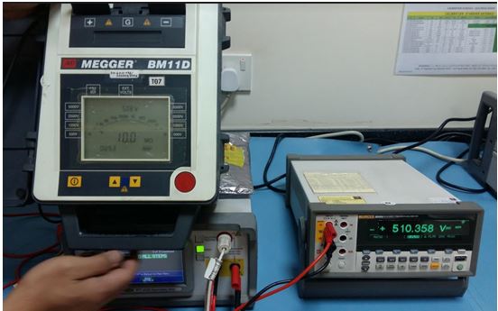
Voltage Function Verification
- Remove the resistor and transfer the probes to the port of the multimeter
- Set the multimeter on the required range ( Vdc)
- Set the Megger on the desired voltage range.
- Push the TEST button of the Megger to generate the voltage.
Readings should be within the specifications provided by the manufacturer.
Megger Insulation Tester Calibration Procedure
Insulation Tester Megger is measuring resistance by generating a voltage and current. Using Ohms Law (V=IR), we can compute the value of the resistance. Because of this, we cannot use a direct simulation of signal like for example from a process calibrator. The process calibrator is also generating a voltage that has an effect on the measured value.
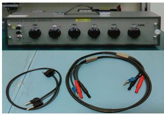
In this procedure, we will be using the Resistance Box to provide an analog resistance for the insulation tester Megger. A Decade resistance box is a set of resistors arranged in such a way to provide a combined resistance reading in a decade interval packed inside a box. (Megger has its own which is called a megger calibration box)
Another reference standard is the Fluke multimeter, we need a high range and resolution multimeter capable of reading the entire range of your Megger. If you cannot reach the entire range, you can still calibrate but with a limited range that is approved by the user.
Calibration Method:
This is accomplished by comparing the decade box’s resistance output to Megger’s display. And also the voltage display in the Megger to the voltage reading of the multimeter. This procedure can be used on all Insulation Tester that accepts an analog resistance.
Requirements:
- Warm-up time (UUC): At least 1 hour for proper stabilization
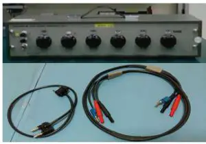
Decade Resistance Box and connecting wires - Temperature: 23 +/- 5 deg C
- Humidity: 50 +/- 30%
- Measurement Data Sheet (MDS) or a Megger Test Report (check this link to learn more about Measurement Data Sheet)
Reference standard to use:
- Decade Resistance Box ( Calibration Box)
- Fluke Precision Multimeter 8846A
- Thermohygrometer ( to monitor Temperature and Humidity)
- Connecting wires
Calibration procedure:
- High voltage is generated in this procedure, always observe safety.
- Check the Megger Tester for any visual defects that can affect its accuracy. Discontinue calibration if any defect is noted.
- Clean the Megger Tester with a soft cloth Check if it has good batteries, replace low-powered batteries.
- Power on the unit and allow stabilization of 1 hour, to be conditioned on the environmental conditions of the room.
- Prepare the measurement data sheet (MDS) and record all necessary details or information (Brand, Model, serial #, etc).
- Determine the test points to be calibrated on the Megger Tester, choose at least 5 test points covering the whole range or as per user range. Record this on the MDS.
- Using Fluke Precision Multimeter, connect the necessary test leads to measure DC Voltage
DC Voltage Verification:
-
- Connect the positive terminal of the Megger to the positive Input HI of the Fluke multimeter and the negative terminal to the LO Return side.
- Set the Megger (Unit Under Calibration) to DC Voltage mode. Select the range of voltage to be generated.
- Press the TEST button to generate each of the required voltage setpoint values.
- Take note of the measured value on the multimeter.
- Wait for the display to stabilize then get the reading. Record readings on the MDS or Megger Test report.
- Take at least 3 trials for each setpoint
- Repeat numbers 2 to 6 until all ranges are covered.
Resistance Verification:
- Remove the connection probes of the Megger that is connected to the multimeter.
- Now connect the probes to the terminal of the Decade resistance box ( same connections as with the multimeter).
- Set the resistance value of the decade resistance box to the desired value by turning the knobs. (an example is 100 Mohm)
- Press the TEST button, the Megger will inject a voltage to the resistor and generate the required resistance value.
- Wait for the display on the Megger to stabilize then get the reading. Record readings on the MDS.
- If the readings are already within limits, update the corresponding record, do labeling and sealing and issue to the owner, otherwise, do necessary repair or adjustment.
8, End of procedure
Based on manufacturers’ Specifications, below are the tolerance limits that can be used.
Voltage reading
±5% of nominal test voltages (load resistance >100 MΩ)
Resistance Reading
±5% 1 MΩ to 100 GΩ at 5 kV
±5% 1 MΩ to 10 GΩ at 500 V
±20% outside these limits (above 100 kΩ)
Example:
Voltage output is 500 Vdc, allowable limits is (0.05×500 = 25 V)
Therefore, the tolerance value is from +/- 25 of 500 or (475 to 525) Vdc
Want to learn how to interpret a calibration certificate properly? Visit my other post, click here.
Conclusion
Understanding Resistance measurements have so many ways and Megger Insulation Tester is one of the instruments that may confuse you or intrigue you if you are new in electrical measurement. In order to be clear in this matter, I have provided a simple explanation of the principle of its measurement. We have known that it is using an analog signal in order to generate the required resistance.
Once you have understood this principle, it is now simple to calibrate or verify an insulation tester. I have presented in this post how to verify a Megger Insulation Tester by using a reference standard Multimeter and a Resistance box. The setup is also applicable to most insulation testers.
Looking for an INSULATION TESTER, Check this page insulation tester.

Thanks for visiting my site, please leave a comment and subscribe.
Edwin
54 Responses
Rohan Perera
Very informative
Thank you
edsponce
Hi Sir,
Your Welcome. I Appreciate you liked it.
Best Regards
Frank Lampard
Useful article sharing blog for insulation tester. Important and informative idea sharing this blog. Guys would love it.
edsponce
Thank you sir, appreciate your comment.
Best regards,
Edwin
Fernando
Just come across with your website and i find it very informative and also it gives me an idea in the calibration of other instruments. I would like to know if calibrating an analogue insulation tester like model specifically Megger BM12 would require a resistance load to be connected across the measuring DVM if you intend to measure the output DC voltage of the Megger BM12?
On the other matter, there are insulation tester like Fluke 150X Series, wherein in the Source Voltage is verified or measured using a Resistance Load (or applied load) of 1 MΩ, 500kΩ, 250kΩ, 100kΩ, and 50 kΩ for tester (DUT) range of 1000 V, 500 V, 250 V, 100 V and 50 V respectively. This was taken for the Fluke 150X Series calibration Manual in the verification test under “Source Voltage Accuracy Test, R- Nominal. Do we require load resistance to be connected to the DVM when checking or verifying the insulation tester output voltage? Does this apply to all the insulation tester of various model? Thank you so much for your attention on this matter.
edsponce
Hi Fernando, I am happy to hear that you have learned from my post.
About your query, if it requires a resistance load to be connected across the DVM to measure its DC voltage output, the answer is it can be but no need, the BM12 will source out a voltage that can be directly read by a multimeter or DVM. You only need a resistance load if you want to get the current generated by the Megger wherein a series connection with the DVM is applied.
The only thing that you need to be aware of when measuring voltage using the DVM is the voltage range, Usually, Insulation Testers can reach up to 15KV or more. Most DVM is designed up to 1000 V only. For this, you need to use a high voltage probe (Fluke 80K-40 High Voltage Probe ).
).
Also, Resistance load are used as a verification standard to check if the resistance measured or displayed by the Megger or insulation tester is accurate or within the acceptable range as I present it in the post. All insulation tester I believe are applicable in this principle because its purpose is to measure the insulation (a high resistance value which is an analog type).
I hope I have answered your query. Please do not hesitate to comment further.
Best Regards,
Edwin
Cheslyn
Thanks this makes life so much easier
edsponce
H Cheslyn, you’re welcome and Thank you also.
Best Regards,
Edwin
Chris Casao
Salamat kabayan. Malaking tulong to sa aking baguhan sa calibration.
edsponce
Walang anuman Kabayan, Salamat sa pag bisita sa aking site. Kung may katanungan mag message lang po.
Maraming salamat.
Edwin
Vijay Rawat
Sir,
One of the best description I have to read or understand.
Really great ful to you sir.
edsponce
Hi Mr. Vijay,
I am happy to know and appreciate your comment. Please let me know other things that I can help you with about calibration.
Best Regards,
Edwin
Sonny Doan
Hi Edwin,
Thank you for posting this good information.
Megger includes a Certificate of Calibration with the test instrument purchase. In the C of C, Megger includes test results of tests such as Voltage Ranges, Continuity Range, Resistance Range, Capacitance Range, and Insulation Range. It is quite difficult for a non-electrical background to interpret their C of C. Your calibration test instruction is logical and easy to follow. Any idea why Megger present their data in such a way?
I assume we can use your instruction for AC voltage verification steps. Thanks.
S. Doan
edsponce
Hi Mr. Sonny,
You are welcome. I am glad you liked it. Thank you for your valuable comment.
Yes, you can also use it in AC, same connection.
My Idea is that since they are the manufacturer, they include all the capabilities of their instruments in full range. If you are not familiar with other parameters or if you are not using it, then understanding them is challenging. Sometimes you need to have training about instrument functionality in order to understand it.
The post that I presented is not the full calibration procedure; I only presented the most measured parameters during Insulation testing. This is to help the user to easily verify the accuracy of the Insulation tester in a step by step process by just checking the resistance and voltage functions with a simple resistance box and a multimeter.
As per my experience working in a cal lab, we assume that the user has the experience and knowledge to understand the COC. But in any case the user cannot understand it, we are open and available to explain it to them as part of our customer support.
Please feel free to send in my email at edwin@calibrationawareness.com the COC so that I can review and make a comment further.
Hope this helps,
Best regards,
Edwin
Majid
Dear sir,
could this calibration instrument calibrate the multimeter (V,A.Ome) ?
thanks
edsponce
Hi Mr. Majid,
Do you refer to the resistance box and multimeter? It can be used to calibrate the resistance (Ohm) unit only. But if you are referring to the insulation tester, no, it cannot be used.
Regards,
Edwin
Majid
Thank you Mr. Edwin for your reply,
could you please advice me to instrument which calibrate both the megger and the mutimeter tester
and how can i get it?
Regards
Hector
How would you go about calibrating a 15KV insulation tester? Is there any recommended decade boxes that can handle 15KV?
edsponce
Hi Hector,
I did not yet explore for a decade box that can handle a 15KV voltage. But in any case, you cannot find one, and you are just concerned about the accuracy of the 15KV insulation resistance range, you can buy a single resistor that can handle the ratings you need then use a multimeter as your reference standard (as shown in the image of my article above). The resistance value should be the same as the displayed value from the multimeter.
Hope this helps,
Thank you for reading my post.
Edwin
Manar
Hi Mr Edwin ,
This article is very helpful to me as Iam new in calibration field ,I want to ask what is the range of the decade resistance box to check and calibrate the megger
edsponce
Hi Manar,
Thank you for visiting my site. I am glad that this article has helped you in some way.
About your concern, for a full range check or calibration with the BM11D Megger, you need up to 10 GΩ resistance.
Resistance Reading as per the manufacturer manual:
— 1 MΩ to 100 GΩ at 5 kV
— 1 MΩ to 10 GΩ at 500 V
Megger has a dedicated resistance box, you can search the model Megger CB101.
Thanks and regards,
Edwin
Manar
Another question I want to ask , could I use a hand held digital multimeter with high accuracy in calibration instead of that one .
edsponce
Hi Manar,
Yes, you can use but it will be limited only up to 1000 Volts.
Most multimeters can only measure up to 1000 Volts. The Insulation testers in my post can generate up to 5KVolts. Because of this, you need additional equipment like a High voltage probe or a Kilovolt meter for voltages above 1000 V.
Hope this helps.
Thanks and regards,
Edwin
Manar
Thanks alot for your help , your site helped me alot in the calibration .
edsponce
Hi Manar,
You are welcome. Happy to know that my articles have helped you.
Thanks and regards,
Edwin
Tanmay Ghadge
This was Really Helpful
edsponce
Hi Tanmay,
I am glad that this article has helped you. I appreciate your comment.
Thanks and regards,
Edwin
Neeraj Patel
Hi Mr Edwin ,
This article is very helpful to me, i just want to know that which standard document i can refer for calibration of insulation resistance.
edsponce
Hi Mr. Neeraj,
You can use Euramet cg-15 and/or the manufacturer procedure.
Thanks for reading my post.
Best Regards,
Edwin
Erwin
Hi Edwin,
Thank you for your clear explanation how to use a decade box
It helped us very well
edsponce
Hello Erwin,
You are welcome. I am glad this article has helped you.
Thanks for reading my post.
Edwin
Umaparvathi M
Hello Sir,
Can you please give us the procedure for HV tester calibration. Thanks in advance.
edsponce
Hi Umaparvathi,
I will try to consider it on my future posts.
Calibration of high voltage tester calibration is the same with power supply, you only need a multimeter that can read a very high voltage range. You can also use ‘high voltage probe’ in combination with an ordinary multimeter to measure high voltage range.
I hope this helps,
Edwin
James Kelly
Thanks for sharing this article. Hope it will help me a lot.
edsponce
Hi James,
You are welcome. Thanks for visiting my site.
Edwin
Nizar alif
Could you please tell me which is the international standard for insulation tester calibration
edsponce
Hi Nizar,
there are no specific international standards for this but you may try to check Euramet cg 15 and IS 13875 (Indian Standard).
Best regards,
Edwin
Roni
uncertainty calculation for insulation tester?
Can you please provide the calibration procedure for primary and secondary injection kit.
edsponce
Hi Roni,
Thanks for reading my post. I will try to create a post about uncertainty calculation in my future posts. May I know your specific concern regarding uncertainty calculation? Is it the main uncertainty calculation or the uncertainty budget only?
Sorry, I did not yet experience calibrating an injection kit but basing it on its function, you can try to use a multimeter, current shunt, a high voltage probe, and a clamp meter.
Thanks and regards,
Edwin
RONI
Hi Erwin,
Is it required to measure the insulation current and continuity short circuit current measurement required in insulation tester calibration?
If required how we can prepare the cmc for the insulation tester?
edsponce
Hi Roni,
It depends on the user’s requirements if the current parameter is important during measurements. But as per the usage of the Insulation tester wherein we primarily measure Resistance with a given voltage, it is not required to measure the “current”. But if ever you want to measure it, you just need to connect a multimeter in series with the Resistor. Or simply calculate the current using “ohm’s law” since resistance and voltage is already given or can be measured directly.
For the CMC, each parameter has a separate uncertainty budget, one for Voltage, Resistance, and Current.
If you already know how to calculate measurement uncertainty, you only need to include the resolution of the UUT in the uncertainty budget for CMC calculation. For example:
1. UUT resolution
2. STD resolution
3. Std uncertainty from the calibration certificate
4. Accuracy of std
5. Stability of std
I hope this helps,
Edwin
Roni
Hi Erwin,
When measuring the insulation voltage (DC Insulation) from the insulation tester by using a multimeter what will be the resistance we need to connect in the circuit.? Is there is any fixed resistance value is there?
edsponce
Hi Roni,
When measuring voltage, you do not need a resistance value. You can directly connect the terminals of the insulation tester to the port of the multimeter. Just make sure the multimeter voltage range can measure the insulation tester’s high voltage output.
If you want to verify the resistance reading of the insulation tester, there are available resistance boxes that you can check, the resistance values range from Megaohm to Giga ohm. Some manufacturers have a fix resistance box dedicated for their insulation tester.
I hope this helps,
Edwin
Roni
Hi Erwin,
As per SANAS TG 02-02 (5.1.2), the voltage measurement should be conducted at the load recommended by the manufacture and we need to mention the load in the calibration certificate.
Can you please clarify?
Thank you
Roni
edsponce
Hi Roni,
Sorry but I need more details to understand your question. You can send a copy of the standard to edwin@calibrationawareness.com for me to review further.
Best regards,
Edwin
Roni
Hi Edwin,
If we are using resistant box and multimeter for measuring the mA current in the insulation testing, how i can prepare the the uncertainty budget. Because we are using 2 instrument one is in ohm and other is in mA. How i can convert it into a single unit in uncertainty budget?
Roni
edsponce
Hi Roni,
I need to see first your uncertainty budget for this.
But for simple analysis, because you are not measuring the resistance, the resistance box will function only as an accessory or a load. No need to include it in the budget. The main standard is the multimeter.
But if you want to calculate the actual current in the resistance box, you can use Ohm’s Law (V=IR), voltage and resistance is given therefore you can calculate the current.
I hope this helps,
Edwin
Roni
Thank you.
edsponce
You’re welcome!
BG
Hi,
Can i use Fluke 5522A to calibrate insulation tester?
edsponce
Hi BG,
No, you cannot use Fluke 5522A. The signal from the 5522A will not be recognized by the Insulation Tester. There are other calibrators from Fluke that are specifically designed for Insulation Testers.
Best regards,
Edwin
Roni
Hi Edwin,
In the uncertainty budget of insulation resistance, what will be the lead wire resistance that will need to be added? we are checking up to 10kv insulation tester (10TOhm).
Thank you
edsponce
Hi Roni,
You need to check the manufacturer’s specifications for this. But when measuring high resistance values, lead resistance is usually negligible. You can try to measure the lead resistance by shorting the leads together.
I hope this helps.
Edwin
Clear Point Intrumentation Pvt. Ltd.
Excellent article — clear, well-structured and extremely practical for calibration engineers. I especially appreciated the detailed step-by-step method for verifying both resistance and voltage functions with a decade resistance box and a precision multimeter. The emphasis on warm-up time, environmental conditions and documentation makes it highly useful for maintaining traceable calibration records. Thank you for sharing such an informative guide.