One of the most utilized components in electronics is the resistor. It is found in every electronics device where its main purpose is to resist or limit the flow of current. This is one of the major uses of a resistor in electronics design and troubleshooting.
But in the calibration field, a resistor has a different purpose. I will present with you the use of a resistor, as a decade resistance box in calibration, as a standard used to verify and even calibrate a measuring instrument.
In this article, I will show the 6 important uses and learn how to use a resistance box in calibration. By being aware that we have this kind of instrument or standard will help us to extend our calibration capability.
I also included a simple calibration setup for a resistance box.
What is a resistance box?
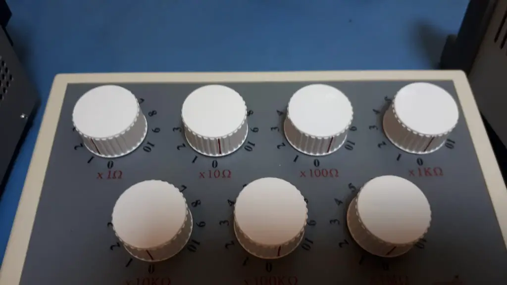
A decade resistance box or simply resistance box is a combination of high accuracy resistors that are arranged inside a box that form a set of resistance ranges which is increased incrementally (mostly in a decade steps).
Resistance boxes have different accuracy ratings and range so better choose the one that is suited for your needs.
Check this link to learn more about resistance box basics.
Below are the 6 important uses of a decade resistance box that I presented here:
- Use to calibrate an RTD transmitter
- Use to calibrate insulation tester
- Use to calibrate a resistivity meter
- Use to verify or calibrate a simple ohmmeter or multimeter
- Use to calibrate a conductivity meter
- Use to verify or calibrate a ground strap/shoe checker
How to Use Decade Resistance Box in Calibration
Learn 6 ways on how to use a decade resistance box by considering the connections as shown in the photo. The resistance box has no polarity so interchanging the port is not a problem.
1. Use to calibrate an RTD transmitter – PT100 simulator
A resistance box can be used to calibrate your RTD Transmitter. RTD utilizes a signal that is dependent on the change of resistance as its sensor. This change of resistance has an equivalent value in temperature.
You just need to determine the equivalent resistance of the temperature to be simulated into the RTD transmitter. A PT100 transmitter or temperature sensor has an equivalent table of resistance to temperature conversion that you can use.
There is a dedicated resistance box for this purpose to ensure that you cover all the resistance range that you will need.
Below is the setup, just replace the RTD sensor with the connecting probe from the resistance box.
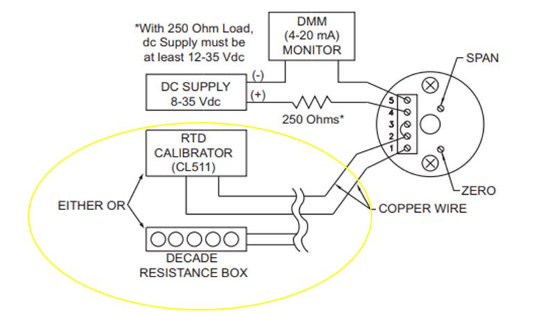
Visit this link for RTD transmitter calibration.
2. Use to calibrate an insulation tester
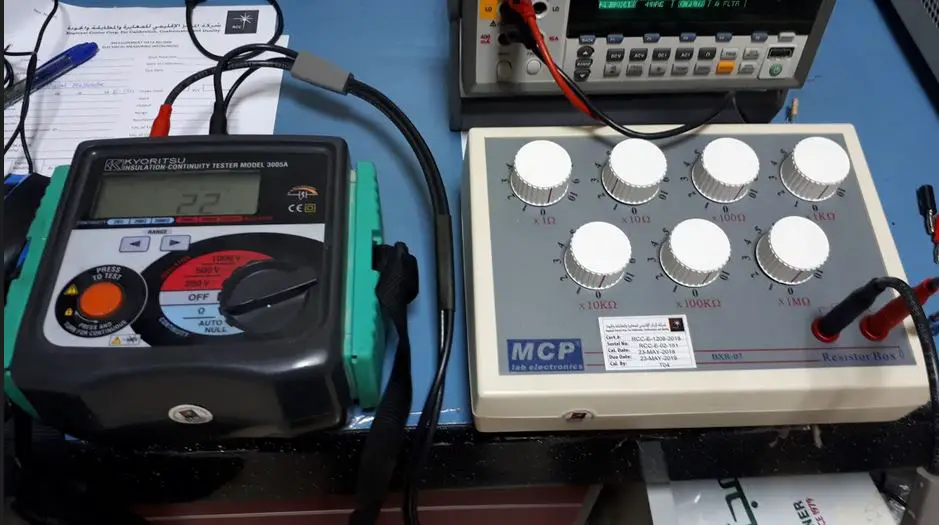
This is the perfect use of a resistance box. Since the insulation tester requires an analog resistance signal (not a digital signal from a process or multi-product calibrator), you can use the decade box as a load for the insulation tester.
The insulation tester will generate a voltage and current that will pass through the resistance box and display the computed resistance value.
For verification purposes, the resistance value should match with the display of the insulation tester and should be within the tolerance specified by the manufacturer.
See below set up.
For the calibration procedure, visit my other post here..Insulation Tester
3. Use to calibrate a resistivity meter
Another important use of a decade resistance box is for calibrating a resistivity meter or controller. This is a direct simulation of resistance in the resistivity meter.
Just apply directly to the required resistance as per the manufacturer’s specification. Make sure to consult the manufacturer manual in order to obtain the exact value of resistance to be used. This is sometimes called a dry calibration.
Some resistivity meter also uses an RTD sensor for temperature monitoring. You can also use the resistance box for this.
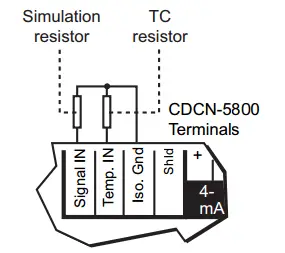
Photo from OMEGA Resistivity Controller manual.
4. Use to verify or calibrate a simple ohmmeter or multimeter
If your resistance box has a high accuracy rating, you can use it to calibrate an ohmmeter or the resistance range of a multimeter. The setup is very simple, it is a direct connection of the resistance box to the port or probe of an ohmmeter or multimeter.
5. Used to calibrate a conductivity meter
Conductance is the opposite of resistance. Most of the sensors have circuitry that converts the resistivity to conductivity, thus, resistivity from a resistance source can be used to calibrate a conductivity meter.
Most conductivity meter or controller has the same calibration setup with its resistivity function.
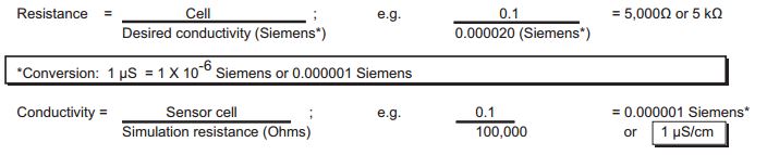
You should also need to check the manufacturer’s manual to determine the needed resistance value to simulate the required conductivity.
Below photo is a sample conversion for resistance to conductivity based on the manufacturer.
6. Use to verify or calibrate a Continuous Grounding Monitor (CGM) with a ground strap or a shoe checker
A ground strap or a shoe checker is used mostly in a semiconductor company to eliminate or minimize ESD or electrostatic discharge by connecting a body to the ground.
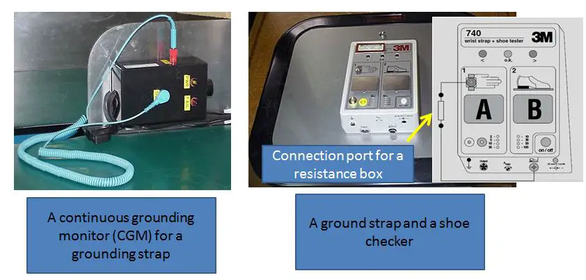
Shoe checker and CGM have a resistance value set to them in order to perform as a good grounding unit or to detect an ungrounded body.
In a CGM, an audible alarm will sound when the desired resistance is not met. Just replace the ground strap connected to the CGM with the probe from the resistance box.
How to calibrate a Decade Resistance Box
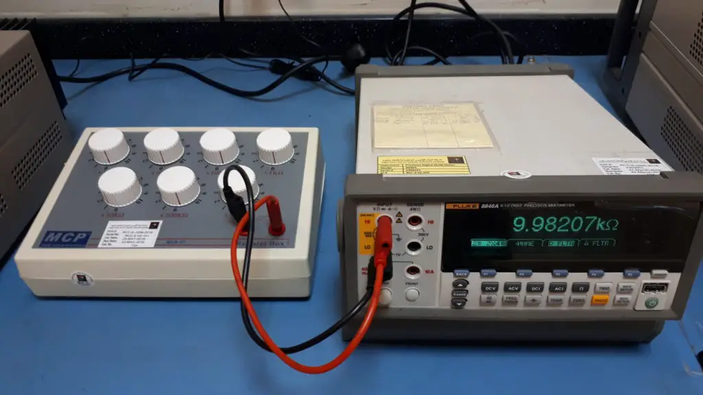
The decade resistance box calibration procedure is very simple; it is the same as a single resistor. The procedure is to verify the accuracy of the resistors installed in the decade resistance box.
The only main reference standard to be used is a precision multimeter, where the resistance value that is set in the knob of the decade box is compared to the display of the multimeter.
For a more accurate measurement especially in the smaller value of resistances, a 4-wire connection should be used.
It is a simple measurement but it takes time because of the number of ranges that we need to cover.
3 Guides to Consider When Choosing a Resistance Box
1. Resistance Range
-
- Resistance range varies depending on your purpose. Based on my experience, the resistance range which you can use for RTD, multimeters, and Resistivity Meters is from 0.01 ohms to 11 Mohms is already fine
- For other types of insulation meters, you can use the 1 Megaohm to 11 Megaohms range.
- For an insulation tester that has a much higher range of resistance, use a separate resistance box. It can reach 10 Gigaohms. Check the example from Amazon (click the photo below).

 2. Power and voltage rating
- The most application has low voltage and low powered ratings, instruments like RTD, multimeter and resistivity meters.
- For insulation testing purposes, voltage rating can range as high as 5000 V or 5kV.
- Check the requirement or specification of your UUC before using the resistance box to avoid damage. Below is a sample rating in terms of power, voltage, and current.
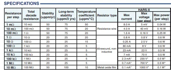
Photo from HARS X series resistance box. These ratings should not be exceeded
Example on How to understand the Specifications of a Resistance Box
- When you test with the 10-ohm range, please make sure the voltage is under 2.5 V, and the current is under 250 mA, in which the power is 0.6 watts.
- To compute manually, you can use Ohm’s law, P=IV
- Some RTD supply ratings are 10 Volts and 0. 8mA. From these specs, you can determine the required resistance box to be used.
3. Accuracy and resolution
- The more accurate and with high resolution, the most expensive. 1% accuracy with 1-ohm resolution is good but 0.01% with 0.001 Ohm resolution is better specifically for calibration purposes.
- For an RTD, most resistance values are on 0.01 resolution, so it is better to choose a 0.01 resolution resistance box.
- for example, the resistance needed for a PT100 at 100 deg C is 138.51 ohms, we should use a resistance box with a 0.01 resolution or more.
Some Important Reminder for More Accurate Resistance Reading
- If you are using a resistance box, specifically in low resistance applications, always consult its calibration certificate for the exact value. A correction factor can be used to offset the error.
- Another option is to always verify the resistance value by using a calibrated multimeter. In this way, you will be sure about its exact value while using the resistance box.
- Zero settings are not always exact, test first the resistance at Zero ohms using a multimeter then subtract this resistance every time you make a resistance simulation or measurement.
- Check first the power or voltage output of the UUC for calibration before using the resistance box. This is to ensure that the resistance box can withstand the voltage or power supplied to it.
Conclusion
I have presented the 6 important uses of a resistance box as an additional standard and capabilities in electrical and temperature calibration. Every cal lab should have this as one of their reference standards because not all UUC (Unit Under Calibration) are using a digital signal from a resistance generator or calibrator. It is a simple device but very helpful in some or most cases.
I also presented the calibration setup of a resistance box where a precision multimeter is used as a reference standard and the things to consider when choosing and using a resistance box.
Additional use of resistance, this is not considered as a resistance box but its function is based on resistance same as a resistor but in a different way. This is called a current shunt.
Do you have other uses of a resistance box in the calibration field? Comment below.
Do not forget to subscribe and share.
Are you looking for a decade resistance box? check this out in Amazon>> Decade Box, Resistance, 7, 1ohm to 11.11111Mohm, 1%
Edwin
24 Responses
Arturo Difuntorum
Thanks, very helpful as usual.
edsponce
Hi Mr. Arturo,
You are welcome. Appreciate your comment.
Best regards,
Edwin
Mário Fonseca
Thanks for time that you have spent for This subject, it was really helpful.
edsponce
you are welcome Mario, appreciate also for your time reading my post.
Thanks and regards,
edwin
Christopher Rodil
Very clear ang understanding details. Thanks
edsponce
You Are welcome. Thank you for reading.
Best Regards,
Edwin
JOHN MULINDI
As an instrument Engineer, this information is important. Thanks for sharing.
edsponce
Hi Mr. John,
You are welcome. Yes, an important tool that must be added to our calibration journey. Thank you for visiting my site.
Best regards,
Edwin
JOHN MULINDI
Your articles are usually filled with practical and easy to follow procedures. As an instrument engineer, I gain so much knowledge and I can also put this into practice with ease. Thanks for sharing.
edsponce
You are welcome Sir,
Appreciate your comments.
Best Regards,
Edwin
saowaluck ukrisdawithid
Do you have appropriate decade box for calibrate conductivity meter? please send me a quatation .
edsponce
Hi Saowaluck,
Sorry to inform you that I am not a supplier of an instrument of any kind.
you may check this link in Amazon.. Resistance box
Thanks for visiting my site.
Edwin
Dimitrij
Very very sexy, thank you baby 😉
edsponce
You are welcome 🙂
Rui
My resistence box
https://photos.app.goo.gl/D7mZj2xpK9HU4hNf7
edsponce
Hi Rui,
You have a good resistance box. It looks like a high-end old model.
Thanks for sharing.
Edwin
Vinod
Hi, thanks for your valuable post. I am unable to understand the relation between Accuracy, Error and uncertainty. Can you tell me with example. Suppose I have a vernier caliper which accuracy mentioned by manufacturer is 0.03 mm then as per my knowledge, I think that the error +/- uncertainty should be less than 0.03 mm. Or its different meaning
edsponce
Hi Vinod,
Below are the relationships between Accuracy, Error, and Uncertainty as per my understanding based on its application:
ACCURACY is the closeness of the UUT reading to the true value (the value of the reference standard). This is usually given in percentage (%) by most manufacturers in their specs.
The formula for accuracy = error/true value *100 (in percentage)
In order to determine this ‘closeness’, we need to calculate the ERROR. Error is the representation of accuracy. The smaller the error, the more accurate the UUT is.
Error can be computed from the formula: ERROR = UUT – Standard
UNCERTAINTY is the quantification of the doubt in a measurement result since there is no exact or perfect result of a measurement. It is a range of values where the true results are located. The smaller the uncertainty, the more accurate the measurement results.
During Uncertainty calculation, we will combine all the valid error contributions. In other words, uncertainty is a combination of many errors. Therefore, depending on the sources of error, some uncertainty results are low and some are high that it can exceed the manufacturer specifications. (you need training for this topic -Measurement Uncertainty Calculation)
As an example, I will present this simple application:
At a reference value of 10 mm, below is the calibration results:
UUC reading = 10.01
Error = 10.01 – 10 = 0.01 mm
To calculate accuracy;
Accuracy = 0.01/10 *100 = 0.1% @ 10mm range
Measurement uncertainty = +/- 0.008
This means that the true value lies between the limits or 10.01 +/-0.008 or (10.002 to 10.0108)
As per verification, 10.01 is within the tolerance interval of 10+/-0.03 or (9.997 to 10.03), therefore it is “pass”
Another interpretation is to include the uncertainty value to the calibration results to determine compliance to specification. This is where your concern regarding the inclusion of uncertainty results in the measurement results.
Error +/- uncertainty is not in all cases less than the accuracy or tolerance limit. If you include uncertainty in the measurement result and your uncertainty results are somewhat large, there is a chance that it may exceed the +/- 0.03 limits. To learn more about this, download this article: ILAC-G8:03/2009 and Guide 98-4.
You can also read related topics in my other post, check it out here >> calibration terms
Thanks for reading my post.
Just comment further if you have more concerns
Best regards,
Edwin
nunia
can i use digital multi-meter to calibrate resistance decade box?
edsponce
Hi Nunia,
Yes, you can. But you need to ensure that your multimeter is more accurate than the decade box specifications.
Thanks for reading my post.
Edwin
Edgar M.
Thanks for discovering your site. I was in the industry for more than a year working in different countries until the pandemic strike. Hoping someday I can back to work again in my field before I retired. From now on I will read and learned every related topic to enhance my knowledge about instrumentation. Keep learning is the key to be successful. You are the best!
edsponce
Hi Edgar,
You are welcome. I appreciate your comments. Thank you.
I am sure you can continue your field of work again. You are correct, continues learning is a key to success, specially in this field where learning will not end as long as new instruments and processes are introduced.
Anything that concerns you about my article, just let me know.
Have a safe day!
Edwin
M. Saleh
Dear Eng. Edwen,
Thank you very much for your great efforts in spreading the culture of calibration, and education in the field of calibration.
edsponce
Hi Sir,
You are welcome. Thanks for reading my posts.
Best regards,
Edwin